Vertical type condensing heat exchanger and heat exchange method thereof

A condensing heat exchanger, condensing heat exchange technology, applied in heat exchanger types, indirect heat exchangers, lighting and heating equipment, etc., can solve problems such as no steam condensation in pipe sections, increased liquid film thickness, and deteriorated heat exchange effects , to achieve the effect of increasing steam flow and disturbance, low manufacturing cost, and increasing cooling reliability

Active Publication Date: 2015-03-04
福建蓝海节能科技有限公司
View PDF5 Cites 2 Cited by
  • Summary
  • Abstract
  • Description
  • Claims
  • Application Information

AI Technical Summary

Problems solved by technology

[0003] However, as the amount of condensation continues to increase in the current shell and tube structure, it is easy to cause the accumulation of condensed liquid film, and the formed thick liquid film covers the heat exchange surface; at the same time, the cooling of the steam in the tube requires a large amount of cooling liquid to wash the heat exchange tube. Due to the small temperature rise of the coolant, a coolant with a higher mass flow rate is required; the steam condenses in the heat exchange tube, and the flow pattern changes continuously, gradually changing from an annular flow to a plug flow, and the bottom of the heat exchange tube may be filled with condensate , resulting in no steam condensation in some pipe sections, and it becomes a single-phase heat exchange
For vertical condensing heat exchangers, there are few designs that use condensation outside the steam tube, mainly because the length of the vertical heat exchange tube is relatively long, and the condensation outside the tube causes the liquid film to grow along the outer wall of the tube, and the thickness of the liquid film continues to increase, resulting in Deterioration of heat transfer effect

Method used


Image

  • Vertical type condensing heat exchanger and heat exchange method thereof

Examples


Embodiment Construction

[0026] The technical solutions of the present invention will be further described in detail below in conjunction with the accompanying drawings and embodiments.

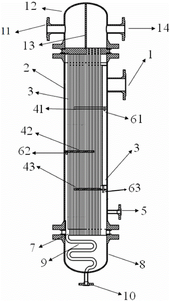
[0027] Such as figure 1 A vertical condensing heat exchanger shown includes a condenser body, a liquid guide pipe and a subcooling pipe, and the condenser body includes a cylinder unit 2 and (first heads) on both sides of the cylinder unit 2 A condensate collector 7 is provided between the head 12 and (the second head) lower head 8, the cylinder unit 2 and the second head 8, and the condensing heat exchange tube bundle 3 and the baffle 4 are arranged on the cylinder unit 2 ;in:

[0028] The cooling liquid flows through the first head 12 and the heat exchange tube bundle 3; the first head 12 is provided with a partition 13, and the first head 12 is located on both sides of the partition 13 and is respectively provided with a cooling liquid inlet 11 and a cooling liquid outlet 14;

[0029] There is a steam inlet 1 a...


PUM


Abstract

The invention provides a vertical type condensing heat exchanger and a heat exchange method thereof. The vertical type condensing heat exchanger comprises a condenser body, an in-tube cooling liquid heat exchange unit and an out-tube steam condensing heat exchange unit. The condenser body comprises a cylinder unit, a heat exchange tube bundle is arranged in the cylinder body, a first head and a second head are arranged on two sides of the cylinder unit respectively, a condensate collector is arranged between the cylinder unit and the second head, an in-tube cooling liquid cooling unit is arranged in the cylinder unit, and the out-tube steam condensing heat exchange unit is arranged on the cylinder unit. Cooling liquid is partitioned by a partition plate in the upper head to flow in two directions, namely from top to bottom and from bottom to top, and absorbs out-tube steam condensing released heat in in-tube travel, high-pressure steam returns to flow in a shell pass to wash a cooling tube transversely to achieve out-tube condensing, and condensate collected by each baffle board is subcooled in the second head, so that reliability of a heat exchange system is guaranteed.

Description

technical field [0001] The invention relates to thermal equipment in the technical field of energy efficient utilization, in particular to a vertical condensation heat exchanger and a heat exchange method thereof. Background technique [0002] The vertical condensing heat exchanger usually adopts a shell-and-tube structure in which "the coolant sweeps across the heat exchange tube and flows from top to bottom, and condenses in the high-pressure steam tube". After the superheated steam enters the condenser, it goes through three processes of cooling, saturated condensation and subcooling, and achieves the purpose of heat exchange by releasing sensible heat and latent heat. [0003] However, as the amount of condensation continues to increase in the current shell and tube structure, it is easy to cause the accumulation of condensed liquid film, and the formed thick liquid film covers the heat exchange surface; at the same time, the cooling of the steam in the tube requires a l...

Claims


Application Information

Patent Timeline
Patent Type & Authority Applications(China)
IPC IPC(8): F28D7/10
Inventor 陆规贾力
Owner 福建蓝海节能科技有限公司
Why Eureka
Try Eureka