Fine particle laser radar system with adjustable focal position and self-calibration method

A laser radar, focus position technology, applied in radio wave measurement systems, instruments, etc., can solve the problems of low adjustment accuracy, poor automation, and low calibration accuracy, and achieve precise adjustment of focus position and focal plane position. The effect of precision and reliability

Active Publication Date: 2015-03-04
HEFEI INSTITUTES OF PHYSICAL SCIENCE - CHINESE ACAD OF SCI
View PDF6 Cites 16 Cited by
  • Summary
  • Abstract
  • Description
  • Claims
  • Application Information

AI Technical Summary

Problems solved by technology

At present, artificial calibration methods and CCD images are mostly used for calibration. There are many human errors and uncontrollable error factors in two-dimensional calibration itself, so there are disadvantages such as low adjustment accuracy and poor automation.
Although the CCD calibration method currently used replaces manual calibration and reduces human error, the calibration accuracy due to the lack of calibration points is not very high.

Method used


Image

  • Fine particle laser radar system with adjustable focal position and self-calibration method
  • Fine particle laser radar system with adjustable focal position and self-calibration method
  • Fine particle laser radar system with adjustable focal position and self-calibration method

Examples


Embodiment Construction

[0015] The present invention will be further described below in conjunction with the accompanying drawings and specific embodiments.

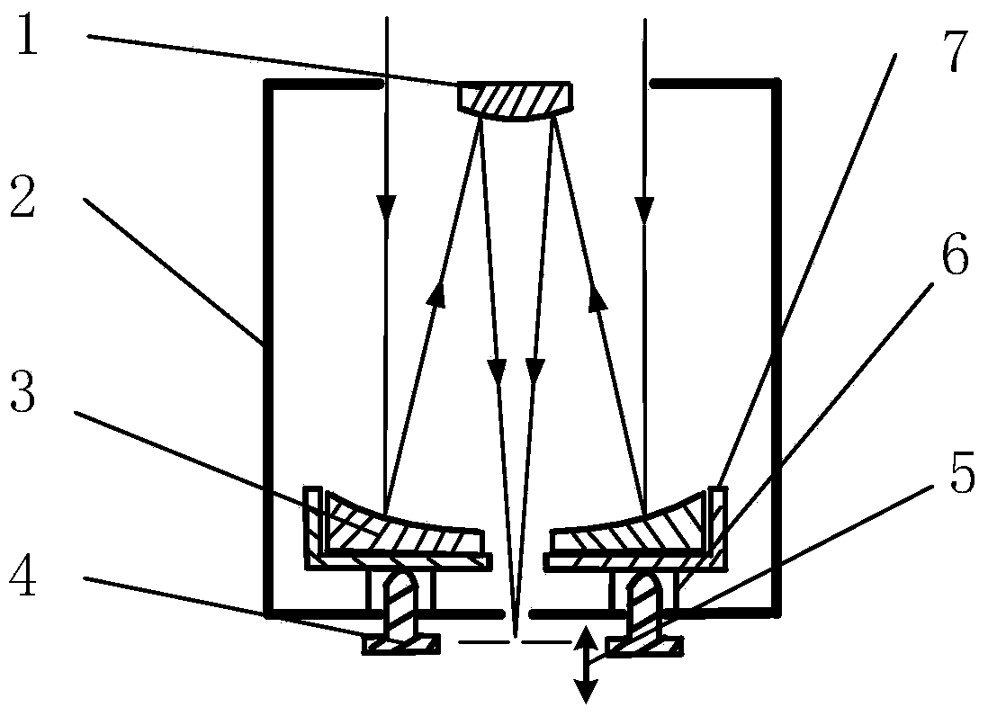
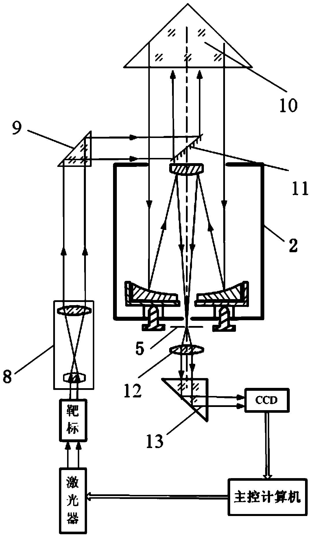
[0016] Schematic diagram of the structure and principle of the receiving optical system of the fine-particle laser radar with adjustable focus position. figure 1 As shown, the receiving optical system includes the receiving system secondary mirror 1, the receiving system main body 2, the primary mirror 3, the adjusting screw 4, the adjustable aperture diaphragm 5, the tension spring 6, and the primary mirror fixing seat 7. The main mirror 3 of the receiving optical system is fixed on the main mirror fixing seat 7 of the receiving optical system, and the adjustment of the main mirror 3 depends on the front and rear rotation of the adjusting screw 4 to adjust the front and rear positions and certain angles of the main mirror 3 of the receiving optical system The adjustment of the focal plane position and the focus position can be adjusted at the ...


PUM


Abstract

The invention provides a fine particle laser radar system with an adjustable focal position and a self-calibration method. The fine particle laser radar system comprises a laser, an imaging CCD (charge coupled device), a control computer, a beam expander (8), a first right-angle reflecting prism (9), a corner reflector (10), a plane mirror (11), a collimating mirror (12) and a second right-angle reflecting prism (13), wherein laser emitted by the laser passes the a beam expander (8), the first right-angle reflecting prism (9), the plane mirror (11), the corner reflector (10), a receiving optical system, the collimating mirror (12) and the second right-angle reflecting prism (13) in sequence and then reaches the imaging CCD; the imaging CCD is connected with the control computer; the control computer controls the laser. The fine particle laser radar system realizes the adjustment of a focal plane and a focal position by adjusting a main primary mirror position, and also realizes a whole set of adjustment process, from rough adjustment to fine adjustment, of the fine particle laser radar system. The self-calibration method replaces manual calibration, overcomes the problem that no target image serves as a reference point, improves the precision, and meanwhile eliminates personal errors caused by manual operation.

Description

technical field [0001] The invention relates to an adjustable focus position and high-precision calibration method in a fine-particle laser radar system, belonging to the field of laser radar. Background technique [0002] Fine particle lidar can monitor parameters such as atmospheric aerosol backscattering coefficient, atmospheric extinction coefficient, atmospheric particle mass concentration, and atmospheric boundary layer height in real time. Atmospheric climatology and atmospheric environmental science research is playing an increasingly important role. [0003] In order to reduce the influence of the blind area on the radar measurement distance, most of them now use coaxial transmitting and receiving devices and concentric transmitting and receiving devices. The telescopic system is an important part of the receiving device, and the index of the receiving optical system is mainly formulated based on the index of the telescopic system. The receiving optical system of ...

Claims


Application Information

Patent Timeline
Patent Type & Authority Applications(China)
IPC IPC(8): G01S7/497
CPCG01S7/497
Inventor 刘洋张天舒范广强赵雪松董云生刘吉瑞
Owner HEFEI INSTITUTES OF PHYSICAL SCIENCE - CHINESE ACAD OF SCI
Why Eureka
Try Eureka