
dcs system for nuclear power plant

A DCS system and nuclear power plant technology, applied in the field of nuclear power, can solve the problems of no DCS system, endanger personal safety, lack of DO modules, etc., to ensure stability and reliability, reduce equipment damage, and enhance economic efficiency

Active Publication Date: 2017-02-15
GUANGXI FANGCHENGGANG NUCLEAR POWER
View PDF6 Cites 0 Cited by
  • Summary
  • Abstract
  • Description
  • Claims
  • Application Information

AI Technical Summary

Problems solved by technology

In actual operation, due to poor contact of the switch fuse of the insurance terminal, easy ground short circuit during the use of the DO module, easy ground short circuit of the wiring between the insurance terminal and the DO module, strong current or short circuit in the cables between the cabinets, etc. , making the possibility of the DO module losing the driving power extremely high
After the DO module loses the driving power, the field equipment loses power, the equipment will be in a closed state, and the field equipment cannot be driven, and the fault cannot be resolved in time, which will seriously affect the safe and reliable operation of the nuclear power plant, and will also cause equipment damage and endanger personal safety.
[0003] In practical application, it is also found that there are the following problems: when the DO module loses the driving power, the DCS system does not have any relevant alarms, and there is a lack of monitoring of whether the DO module is powered off
According to the principle of rapid troubleshooting, the fault cannot be identified, let alone accurate and timely troubleshooting, the system is in a fault state for a long time, and the reliability drops sharply

Method used


Image

  • dcs system for nuclear power plant
  • dcs system for nuclear power plant
  • dcs system for nuclear power plant

Examples


Embodiment Construction

[0020] In order to have a clearer understanding of the technical features, purposes and effects of the present invention, the specific implementation manners of the present invention will now be described in detail with reference to the accompanying drawings.

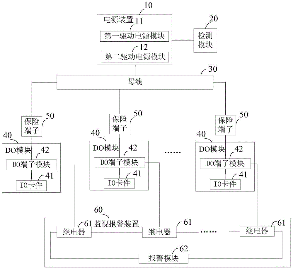
[0021] figure 1 It shows a DCS system for nuclear power plants in an embodiment of the present invention, which includes a power supply device 10 , a detection module 20 , a bus bar 30 , several DO modules 40 , several safety terminals 50 and a monitoring and alarm device 60 .

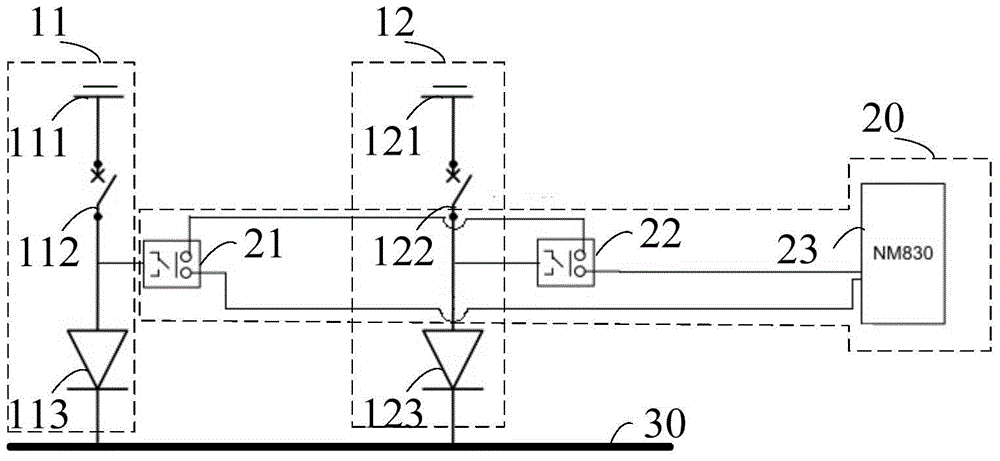
[0022] The power supply device 10 is used to supply power to the DO module 40 , and the power output terminal of the power supply device 10 is connected to the bus bar 30 . Alternatively, the power supply device 10 is a dual redundant power supply device. Preferably, the power supply device 10 includes a first driving power supply module 11 and a second driving power supply module 12, combined with figure 2 As shown, the first driving power s...


PUM


Abstract

The invention discloses a DCS for a nuclear power station. The DCS comprises a plurality of DO modules for sending digital quantity signals in an instrument control system to an onsite instrument, and a power supply device for supplying power to the DO modules. The power output end of the power supply device is connected with a bus, and each DO module is connected with the bus through a fuse terminal so as to obtain power; and the DCS system further comprises a monitoring alarm device for monitoring whether power failure occurs in the DO modules and emitting alarm signals when the power failure occurs in the DO modules. The DCS for the nuclear power station can be used for monitoring whether the power failure occurs in the DO modules and emitting the alarm signals when the power failure occurs in the DO modules, such that the monitoring defect of a conventional DCS is improved, the stability and reliability of the DCS for the nuclear power station are ensured, the probabilities of power station tripping and reactor shutdown caused by incapability of controlling field equipment due to loss of a driving power supply are greatly reduced, the equipment utilization rate is effectively improved, the equipment utilization economic benefits are enhanced, and the risks of equipment damage and personal damage are reduced.

Description

technical field [0001] The invention relates to the field of nuclear power, in particular to a DCS system for nuclear power plants. Background technique [0002] The DO module is a module in the DCS system for nuclear power plants that is mainly responsible for sending digital signals to the field, and is an indispensable part of the DCS control function. In actual operation, due to poor contact of the switch fuse of the insurance terminal, easy ground short circuit during the use of the DO module, easy ground short circuit of the wiring between the insurance terminal and the DO module, strong current or short circuit in the cables between the cabinets, etc. , making it very likely that the DO module will lose its driving power. After the DO module loses the driving power, the field equipment loses power, the equipment will be in a closed state, and the field equipment cannot be driven, and the fault cannot be resolved in time, which will seriously affect the safe and relia...

Claims


Application Information

Patent Timeline
Patent Type & Authority Patents(China)
IPC IPC(8): G21D3/06
CPCG21D3/06Y02E30/00
Inventor 赵盛凯史政林邹志励宋晓龙刘世银
Owner GUANGXI FANGCHENGGANG NUCLEAR POWER
Learn More