Vehicle having a battery arrangement

A battery device and vehicle technology, applied in the direction of electric power device, battery, battery/battery traction, etc., can solve the problem of expensive cooling device and achieve the effect of simple structure

Active Publication Date: 2015-03-04
AUDI AG
View PDF10 Cites 2 Cited by
  • Summary
  • Abstract
  • Description
  • Claims
  • Application Information

AI Technical Summary

Problems solved by technology

[0007] In this case, the fact that the described cooling device is relatively expensive should be regarded as a disadvantage

Method used


Image

  • Vehicle having a battery arrangement
  • Vehicle having a battery arrangement
  • Vehicle having a battery arrangement

Examples


Embodiment Construction

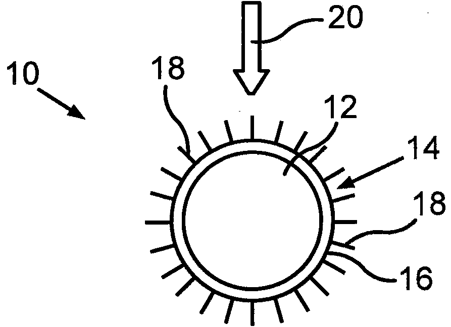
[0039] figure 1 A battery arrangement 10 is shown which comprises individual battery cells 12 as battery cells. Such a battery cell 12 can be designed, for example, as a lithium-ion battery cell which supplies electrical energy for an electric drive motor of the vehicle. The battery cells 12 are surrounded by a housing 14 , which, like the battery cells 12 , is circular in cross section. A plurality of cooling fins 18 are formed in one piece with the wall 16 of the housing 14 and protrude radially from the wall 16 around the outer circumference.

[0040] Housing 14 with cooling fins 18 serves as a cooling device for battery cells 12 . The cooling device is arranged in the load path of the vehicle in such a way that the cooling fins 18 deform when forces are applied to the vehicle due to an accident. The load path is in figure 1 Indicated by arrow 20.

[0041] in accordance with figure 1 In the battery arrangement 10 shown, the cooling fins 18 are also used in a targeted ...


PUM


Abstract

The invention relates to a vehicle having at least one battery arrangement (10), which comprises at least one battery unit (12) and a cooling device for dissipating heat from the at least one battery unit (12). The cooling device is arranged in a load path (20) of the vehicle in such a way that the cooling device can be deformed in the event of an application of force to the vehicle caused by an accident. For this purpose, the cooling device comprises a plurality of cooling ribs (18) around which cooling air flows during cooling operation of the cooling device.

Description

technical field [0001] The invention relates to a vehicle having at least one battery arrangement comprising at least one battery cell and a cooling / radiation device for dissipating heat from the at least one battery cell. In this case, the cooling device is arranged in the load path of the vehicle in such a way that it can deform when forces are applied to the vehicle as a result of an accident. The cooling device comprises a plurality of cooling fins / radiating fins which are circulated by cooling air during the cooling operation of the cooling device. Background technique [0002] DE 10 2008 024 291 A1 describes a passenger car with a floor, which has cross members and side skirts as well as side members in the passenger compartment area. In the area surrounded by these beams a battery can be arranged for closing the body. The battery also assumes the functions of closing the body and carrying the load. For cooling, the battery can have a cooling body with cooling fins ...

Claims


Application Information

Patent Timeline
IPC IPC(8): B60K1/04H01M2/10B60L50/64
CPCH01M10/5004B60K1/04B60K2001/005H01M10/5016B60Y2306/01H01M2/1077H01M10/5063H01M10/5046H01M10/6551H01M10/6561H01M10/613B60L50/66H01M10/625Y02T10/70Y02E60/10H01M50/249B60L50/64H01M2220/20
Inventor C·阿尔曼M·舒斯勒
Owner AUDI AG
Why Eureka
Try Eureka