
Measurement and control device and measurement and control method of on-demand micro-droplet injection process based on image processing

An on-demand micro, image processing technology, applied in the field of on-demand jet printing, can solve the problems of time-consuming and labor-intensive metal micro-droplet jetting devices, difficulty in meeting precise control requirements, and inability to guarantee the stability of jetting process in real time, so as to avoid Low accuracy, avoid time-consuming and labor-intensive effects

Inactive Publication Date: 2016-05-18
NORTHEAST FORESTRY UNIVERSITY
View PDF6 Cites 0 Cited by
  • Summary
  • Abstract
  • Description
  • Claims
  • Application Information

AI Technical Summary

Problems solved by technology

[0005] The purpose of the present invention is to solve the problem that it is time-consuming and labor-intensive to gradually reach a stable state by manually adjusting the metal micro-droplet spraying device, and the stability of the spraying process cannot be guaranteed in real time, and it is difficult to meet the precise control requirements. The present invention provides a method based on Measurement and control device and measurement and control method for on-demand micro-droplet spraying process based on image processing

Method used


Image

  • Measurement and control device and measurement and control method of on-demand micro-droplet injection process based on image processing
  • Measurement and control device and measurement and control method of on-demand micro-droplet injection process based on image processing
  • Measurement and control device and measurement and control method of on-demand micro-droplet injection process based on image processing

Examples


specific Embodiment approach 1

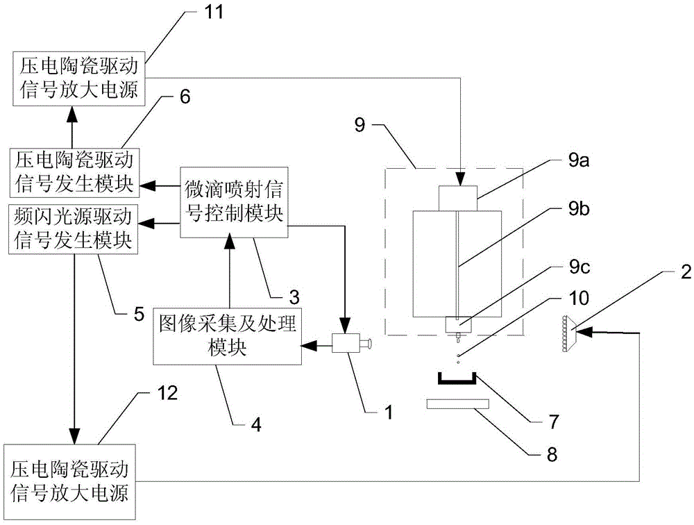
[0031] Specific implementation mode one: combine figure 1 Describe this embodiment, the measurement and control device of the on-demand droplet ejection process based on image processing described in this embodiment, the device includes a camera 1, a strobe light source 2, a droplet ejection signal control module 3, image acquisition and Processing module 4, frequency light source drive signal generation module 5, piezoelectric ceramic drive signal generation module 6, piezoelectric ceramic drive signal amplification power supply 11 and frequency light source drive signal amplification power supply 12;

[0032] The photographing device 1 and the stroboscopic light source 2 are placed on the same level as the nozzle 9c of the metal droplet ejection device 9, and the photographing device 1 is controlled by the droplet ejection signal control module 3 to shoot the metal droplets sprayed by the nozzle 9c, and the stroboscopic light The source 2 is used for the background light whe...

specific Embodiment approach 2

[0039] Specific embodiment 2: This embodiment is the measurement and control method of the measurement and control device of the on-demand micro-droplet ejection process based on image processing described in the specific embodiment 1. Before the metal micro-droplet ejection device 9 starts to perform droplet ejection, the The molten metal recovery device moves to directly below the nozzle 9c; after the metal material to be printed is heated to the set temperature and kept warm in the on-demand metal droplet ejection device 9, the following method is started;

[0040] The method comprises the steps of:

[0041] Step 1: The droplet ejection signal control module 3 controls the piezoelectric ceramic drive signal generation module 6 to drive the piezoelectric ceramic transducer 9a with the set initial piezoelectric ceramic drive signal to generate axial stretching vibration; at the same time, control the stroboscopic light source drive signal The generating module 5 sends a strob...

Embodiment

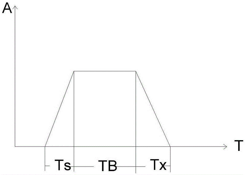
[0058] In order to obtain a stable micro-droplet ejection process that meets the deposition requirements, the mechanical vibration process generated by the piezoelectric ceramic transducer 9a under the action of the driving waveform signal is very important. The present invention adopts the trapezoidal wave as the drive signal waveform of the piezoelectric ceramic transducer, such as image 3 . The driving trapezoidal wave is divided into three parts according to the driving effect: the Ts stage is the stage where the piezoelectric ceramic transducer is deformed under the action of the signal to drive the vibrator to push out. This stage is the stage where the micro-droplets are forced to eject from the nozzle. The length of Ts affects the injection speed; Tb is that the waveform signal reaches the amplitude and remains stationary, so the vibrator also remains at rest for a certain period of time. At this time, the molten metal continues to be ejected with inertia, and this st...


PUM


Abstract

The invention discloses a measuring and controlling device for on-demand micro drop injection process based on image processing and a measuring and controlling method thereof and belongs to the on-demand injection printing technical field. In order to solve the problems the time and energy are wasted for manually regulating the metal micro drop injection device for gradually achieving the stable state, the stability of the injection process cannot be guaranteed at real time and the accuracy control requirement is difficult to achieve. The shooting device and the stroboscopic light source being synchronous with the micro drop injection are adopted for obtaining the real time image of the micro drop injection process, the image is processed by an image collecting and processing module for obtaining the real time information of the micro drop injection process, a micro drop injection signal module 3 judges whether the index of the metal micro drop satisfies the preset condition according to the image extractive characteristic, and the micro drop injection signal control module changes the corresponding parameter of the drive signal for adjusting until that the index satisfies the presser condition; injecting, printing and depositing. The metal micro drop injection device is regulated for gradually achieving the stable state for the on-demand injecting and printing operation.

Description

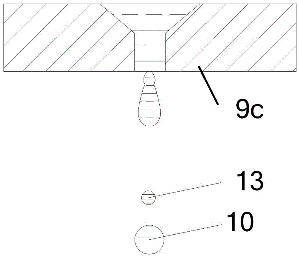
technical field [0001] The invention belongs to the technical field of on-demand jet printing. Background technique [0002] In the process of using on-demand jet printing technology for jet deposition printing of metal parts and interconnection bump printing of microelectronic packaging, it is necessary to precisely control the deposition of metal microdroplets on the substrate at a certain size and speed to ensure the smoothness of the molding process. stability and precision. The metal micro-droplets are driven by the piezoelectric ceramic transducer to generate axial vibration, and the metal micro-droplets are squeezed out of the tiny nozzle. The size of the metal micro-droplets is generally related to the diameter of the nozzle, but through the control The drive waveform for driving piezoelectric ceramics can precisely control the injection process of metal micro-droplets, remove satellite droplets 13, precisely control the size, injection speed, and shape of sprayed m...

Claims


Application Information

Patent Timeline
Patent Type & Authority Patents(China)
IPC IPC(8): B22F3/115
Inventor 吴妍高胜东李艳娟张健刘荣辉
Owner NORTHEAST FORESTRY UNIVERSITY
Learn More