
Rotational cutting tool capable of assembling and disassembling

A technology of rotating cutters and slewing grooves, which is applied in the direction of milling cutters, manufacturing tools, metal processing equipment, etc., can solve the problems of low coupling force of matching parts, brittle cracks of hard alloy rods, low processing efficiency, etc., and achieve stable and reliable positioning Effect

Active Publication Date: 2015-03-11
ZHUZHOU CEMENTED CARBIDE CUTTING TOOLS CO LTD
View PDF7 Cites 2 Cited by
  • Summary
  • Abstract
  • Description
  • Claims
  • Application Information

AI Technical Summary

Problems solved by technology

[0002] Only the cutting part of the rotary tool participates in the cutting during the machining process, and the clamping handle does not participate in the cutting. In order to avoid the damage of the cutting part and cause the entire rotary tool to be scrapped, and to prolong the service life of the rotary tool, the cutting part and the clamping part of the rotary tool are used in the industry. The holding handle is set independently, and the cutting part and the holding handle are connected by ordinary threads to realize repeated loading and unloading of the cutting part on the holding handle. Due to the working conditions and the requirements for processing quality, the holding handle usually needs to be Carbide is made of high-quality alloy, but there are problems such as processing difficulty, low processing efficiency, and high processing cost in processing inner hole threads in cemented carbide. In the prior art, an insert is usually added between the cutting part and the handle of the tool holder. The common insert The insert is a stepped cylindrical shape, which is inserted into the handle of the tool sleeve through interference fit. However, if the interference is large, the carbide rod will be brittle due to high hardness, and if the interference is small, it will lead to brittle cracks between the fittings. The connection force between them is not large, and when the cutting parts bear a large external load, it is easy to slide or even pull out the insert

Method used


Image

  • Rotational cutting tool capable of assembling and disassembling
  • Rotational cutting tool capable of assembling and disassembling
  • Rotational cutting tool capable of assembling and disassembling

Examples


Embodiment Construction

[0030] The present invention will be further described in detail below in conjunction with the accompanying drawings and specific embodiments.

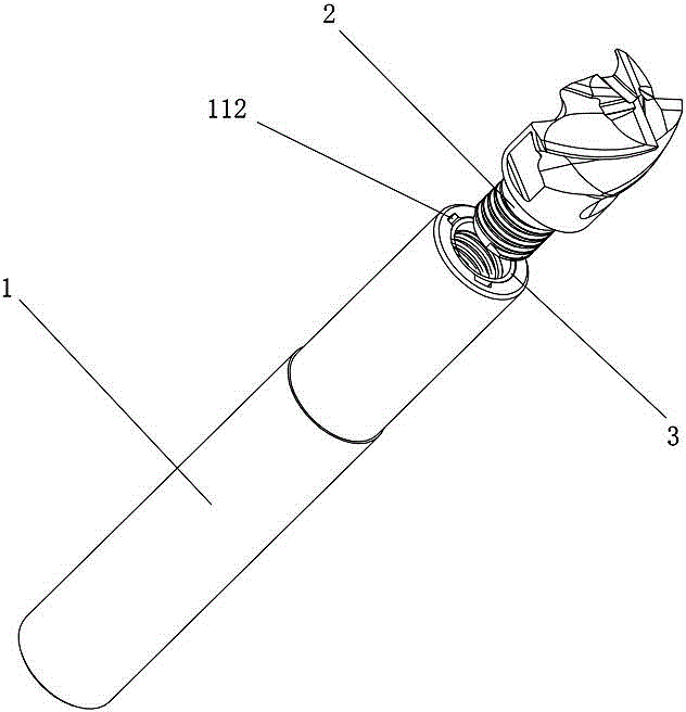
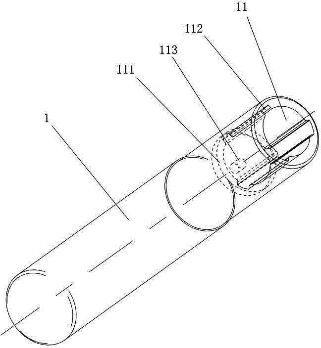
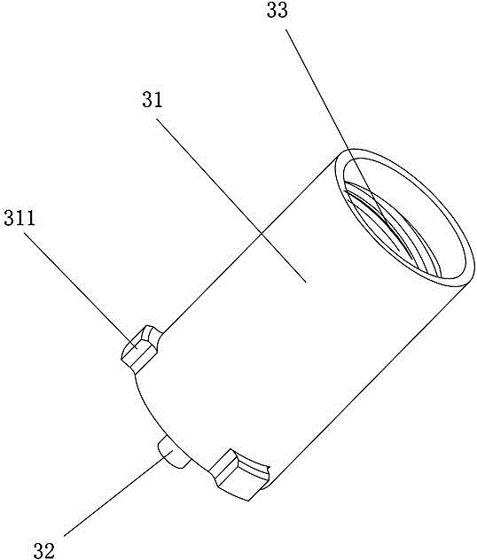
[0031] Figure 1 to Figure 5 The first embodiment of the detachable rotary tool of the present invention is shown, the detachable rotary tool of this embodiment includes a clamping part 1, a cutting part 2 and an embedded connecting piece 3, and the clamping part 1 includes a clamping head and The handle is clamped, and the end surface of the clamping head is provided with an axial recess 11 for installing the inserting connector 3, and the inserting connector 3 is installed in the axial recess 11, and the cutting part 2 is installed on the insert On the connector 3, at least one protrusion 311 is provided on the curved surface 31 of the outer wall of the connector 3, and a rotary groove 111 is opened on the bottom side wall of the axial recess 11, and on the side wall of the axial recess 11 There are axial grooves 112 which have the...


PUM


Abstract

The invention discloses a rotational cutting tool capable of assembling and disassembling. The rotational cutting tool comprises a clamping component, a cutting component and an embedded connecting component, wherein the clamping component comprises a clamping head and a clamping handle, an axial recess is formed in the end face of the clamping head and is used for mounting the embedded connection component, the embedded connection component is arranged in the axial recess, the cutting component is arranged on the embedded connection component, at least one bulge part is arranged on an external wall curved surface of the embedded connection component, a revolving slot is formed in the side wall of the bottom of the axial recess, axial grooves are formed in the side wall of the axial recess, the number of the axial grooves is equal to the number of the at least one bulge part, the at least one bulge part can pass through the axial grooves and is mounted in the revolving slot, an axially protruded locating shaft is arranged at the center of the bottom of the embedded connecting component, a locating hole is formed in the bottom of the axial recess and is not concentric with the axial recess, and the locating shaft is arranged in the locating hole. The rotational cutting tool capable of assembling and disassembling has the advantages of high convenience in assembly and disassembly and reliability in location.

Description

technical field [0001] The invention relates to a cutting tool, in particular to a detachable rotary tool. Background technique [0002] Only the cutting part of the rotary tool participates in the cutting during the machining process, and the clamping handle does not participate in the cutting. In order to avoid the damage of the cutting part and cause the entire rotary tool to be scrapped, and to prolong the service life of the rotary tool, the cutting part and the clamping part of the rotary tool are used in the industry. The holding handle is set independently, and the cutting part and the holding handle are connected by ordinary threads to realize repeated loading and unloading of the cutting part on the holding handle. Due to the working conditions and the requirements for processing quality, the holding handle usually needs to be Carbide is made of high-quality alloy, but there are problems such as processing difficulty, low processing efficiency, and high processing ...

Claims


Application Information

Patent Timeline
IPC IPC(8): B23C5/22
CPCB23C5/2295B23C5/26
Inventor 江爱胜王社权刘敏魏蕊妮易为赵志伟王东海
Owner ZHUZHOU CEMENTED CARBIDE CUTTING TOOLS CO LTD
Learn More