
Walking type self-balancing rotating workbench

A rotating table and self-balancing technology, which is applied in the direction of workbench, metal processing, manufacturing tools, etc., can solve the problems of convenience, safety, and rapidity that cannot meet the requirements of use, cannot be tested, quality treatment, and high equipment cost. Achieve the effect of fewer transmission links, simple structure and less operation workload

Active Publication Date: 2015-03-11
THE GENERAL DESIGNING INST OF HUBEI SPACE TECH ACAD
View PDF6 Cites 13 Cited by
  • Summary
  • Abstract
  • Description
  • Claims
  • Application Information

AI Technical Summary

Problems solved by technology

[0002] At present, in the field of rapid assembly technology, the flow assembly line decomposes each station to meet the large-scale rapid installation, but the equipment cost is high, and the interval between each station is short, so it is impossible to test and quality control between stations
The existing integrated circuit assembly can realize multi-station conversion and installation, but it is only applied to products with light weight and simple assembly process, and the interval between each station is short, so it is impossible to perform testing and quality treatment between stations
However, for high-value products such as large-scale precision instruments and equipment, molds, and models that involve testing, quality treatment, and long assembly cycles in the assembly process, the above two fast filling methods cannot meet the use requirements in terms of convenience, safety, and speed.

Method used


Image

  • Walking type self-balancing rotating workbench
  • Walking type self-balancing rotating workbench
  • Walking type self-balancing rotating workbench

Examples


Embodiment Construction

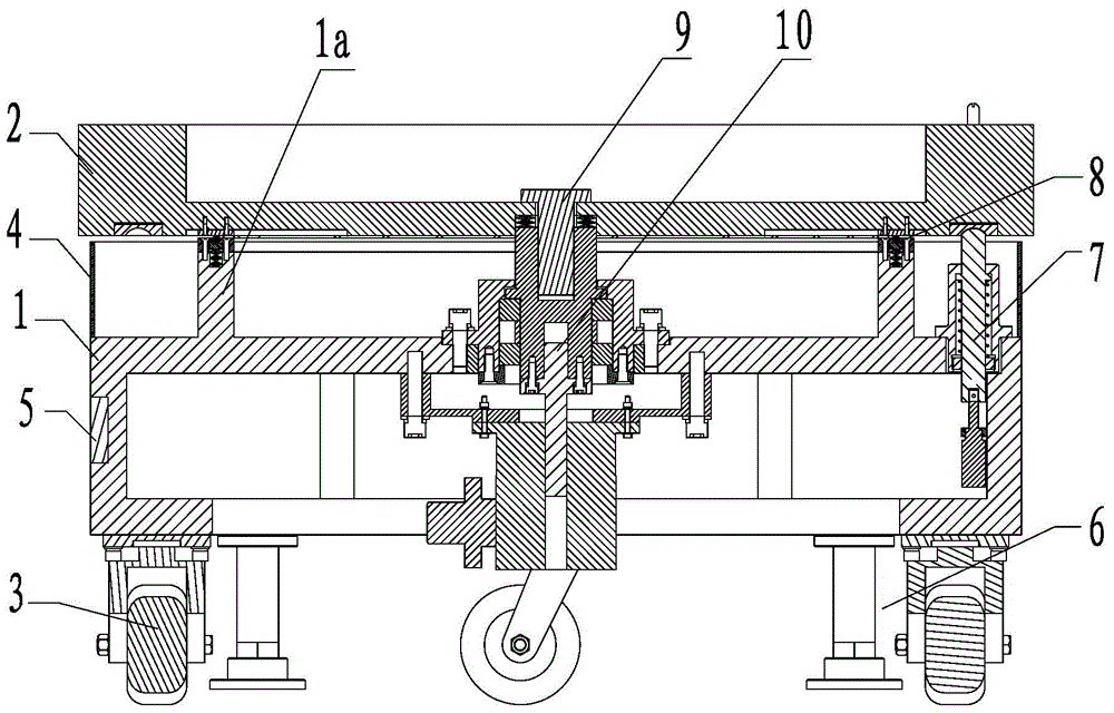
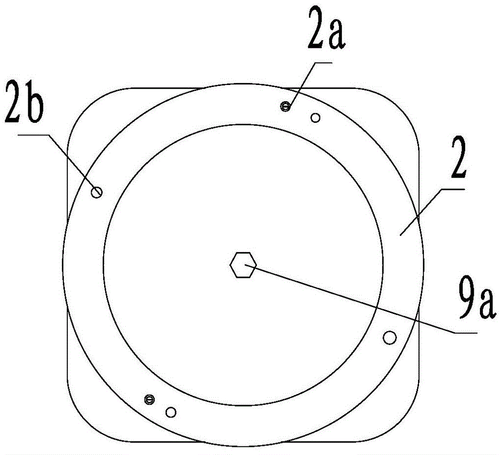
[0022] The walking self-balancing rotary table of the present invention will be described in further detail below in conjunction with the accompanying drawings and specific embodiments.

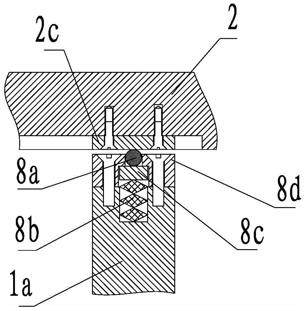
[0023] Such as figure 1 and figure 2 The walking self-balancing rotary workbench shown is used for the support and rotary station transformation of the products to be assembled on the rapid assembly line. Foot 6; walking wheel 3 is a universal walking wheel with self-locking function; supporting foot 6 is a height-adjustable supporting foot; supporting ring platform 1a is arranged on the top of bearing frame 1, and main supporting module 8 is arranged on supporting ring platform 1a , the main supporting module 8 is equipped with a rotating mounting platform 2; the middle part of the bearing frame 1 is provided with a drive and transmission module 10, the upper end of the driving and transmitting module 10 is connected with the auxiliary supporting module 9, and the center of the auxiliary s...


PUM


Abstract

The invention discloses a walking type self-balancing rotating workbench which is used for converting the supporting and rotating stations of a to-be-assembled product on a quick assembling production line. The walking type self-balancing rotating workbench comprises a loading frame, wherein walking wheels and supporting feet are arranged at the bottom of the loading frame; a supporting ring platform is arranged at the top of the loading frame; a main supporting module is arranged on the supporting ring platform; a rotating mounting platform is mounted on the main supporting module; a driving and transmitting module is arranged on the middle part of the loading frame; the upper end of the driving and transmitting module is connected with an auxiliary supporting module; the auxiliary supporting module is connected with a central hole of the rotating mounting platform, so that the auxiliary supporting module is driven to rotate around the center; a positioning and locking module is arranged on a lateral part of the loading frame; the positioning and locking module is matched with the bottom surface of the rotating mounting platform, so that the positioning, locking and unlocking on different rotating stations are controlled. The device is simple in structure, convenient in operation, high in safety and fit for the quick assembling of a large-size precise instrument having a long assembling period and needing to be tested and checked during an assembling process.

Description

technical field [0001] The patent of the invention belongs to the technical field of rapid assembly, and specifically refers to a walking self-balancing rotary workbench. Background technique [0002] At present, in the field of rapid assembly technology, the flow assembly line decomposes each station to meet the large-scale rapid installation, but the equipment cost is high, and the interval between each station is short, and the test and quality treatment between stations cannot be carried out. The existing integrated circuit assembly can realize multi-station conversion and installation, but it is only applied to products with light weight and simple assembly process, and the interval between each station is short, so it is impossible to perform testing and quality treatment between stations. However, for high-value products such as large-scale precision instruments and equipment, molds, and models that involve testing, quality treatment, and long assembly cycles in the a...

Claims


Application Information

Patent Timeline
Patent Type & Authority Applications(China)
IPC IPC(8): B25H1/10B25H5/00
CPCB23P19/00B25H1/0042B25H1/08B25H1/14B25H5/00
Inventor 张正义徐国伟汪文龙孙葵胡胜云
Owner THE GENERAL DESIGNING INST OF HUBEI SPACE TECH ACAD
Learn More