PET bottle flake or thin film drying device

A drying device and bottle flake technology, which is applied in the field of drying devices, can solve the problems of large pipe-side resistance, poor moisture removal effect and high energy consumption of spiral pipes, and achieves lower production cost, lower energy consumption, and good moisture drainage. Effect

Inactive Publication Date: 2015-03-11
JIANGSU ASG PACKAGING MACHINERY GRP
View PDF5 Cites 0 Cited by
  • Summary
  • Abstract
  • Description
  • Claims
  • Application Information

AI Technical Summary

Problems solved by technology

The disadvantages of the pipeline drying device are: 1. The water vapor formed by the heated water on the PET film in the spiral pipeline cannot be discharged in time in the spiral pipeline, and the water vapor can only be separated from the cyclone after entering the cyclone separator with the PET film. Part of the water vapor entering the cyclone separator will be sent to the next section of the spiral pipeline along with the PET film. The dehumidification effect of the whole pipeline drying device is poor. In order to overcome the defect of poor dehumidification effect , the pipeline drying device must extend the drying pipeline, that is, set up multi-section spiral pipelines, which in turn leads to bulky pipeline drying equipment and extremely high energy consumption; 2. Spiral pipelines are easy to form material accumulation at the corners and cause blockage , needs to be cleaned frequently; 3. The pipe resistance of the spiral pipe is large, which is not suitable for drying PET bottle flakes

Method used


Image

  • PET bottle flake or thin film drying device
  • PET bottle flake or thin film drying device

Examples


Embodiment Construction

[0014] The present invention will be further described in detail below with reference to the drawings and preferred embodiments.

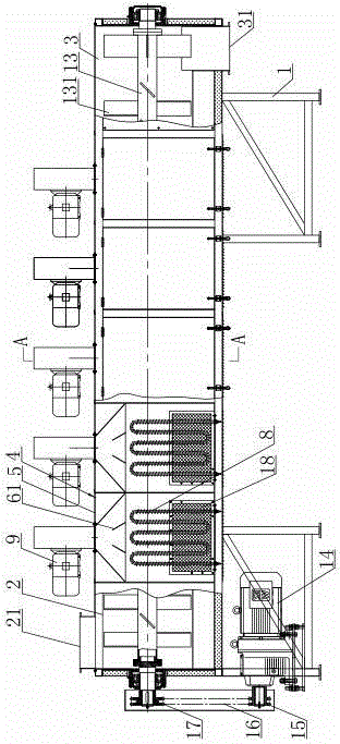
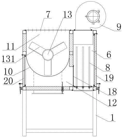
[0015] Such as figure 1 , figure 2 As shown, the drying device for PET bottle flakes or film includes: a frame 1, where a feeding box 2 and a discharging box 3 are arranged on the frame 1, and a feeding port 21 is arranged on the top of the feeding box 2, and the discharging The bottom of the box 3 is provided with a discharge port 31, and at least two drying box units 4 are provided between the feeding box 2 and the discharging box 3. The number of drying box units 4 can be set according to actual needs. The structure of the dry box unit 4 includes: a housing 5, the inner cavity of the housing 5 is divided into a drying chamber and a heating chamber 6, and the heating chamber 6 is provided with a heater. The heater in this embodiment is an electric heating tube 8. The housing 5 at the top of the heating chamber 6 is provided with a fan 9 which cont...


PUM


Abstract

The invention discloses a PET bottle flake or thin film drying device with low energy consumption, quick drying and small size; the drying device includes that at least two drying box units are arranged between a feeding box and a discharging box on a rack; the structure of each drying box unit includes a shell body having an inner cavity divided into a drying chamber and a heating chamber, each heating chamber is internally provided with a heater, the top of each heating chamber is provided with a draught fan, each drying chamber is internally provided with a circular arc separating plate having the bottom protruding downwards and having a plurality of through holes, each drying chamber is separated into a drying upper chamber and a drying lower chamber by the circular arc separating plate, and a shell body of the top of each drying upper chamber is provided with a plurality of wet discharge holes; the drying chambers are communicated with the heating chambers respectively; a stirring shaft with spiral blades successively passes through the feeding box, the drying upper chambers of the drying box units, and the discharging box which are successively communicated with one another, and the stirring shaft is rotated under driving of a stirring driving device, so as to make a material in the feeding box continuously go forwards to be successively outputted from a discharge port of the discharging box through the drying upper chambers.

Description

Technical field [0001] The invention relates to a drying device for drying PET bottle flakes or films. Background technique [0002] In the production process of plastic recycling and granulation, the PET bottle flakes or film formed by crushing need to be washed, dewatered and dried in sequence. Granulation requires that the moisture content of PET flakes or films after drying be controlled within 5%. At present, in the process of plastic recycling and granulation production, the PET film is dried by a pipeline drying device. There are several spiral pipes in the pipeline drying device. A cyclone separator is connected between two adjacent spiral pipes. Each spiral pipe is filled with high-temperature and high-pressure air, and the PET film enters each spiral pipe in turn. In the pipes and cyclones, the water on the PET film is heated in each spiral pipe to form water vapor. After the PET film mixed with water vapor enters the cyclone separator, the PET film is separated by th...

Claims


Application Information

Patent Timeline
IPC IPC(8): B29B13/06
Inventor 施华军黄振华赵慧民惠丽
Owner JIANGSU ASG PACKAGING MACHINERY GRP
Why Eureka
Try Eureka