Eureka AIR delivers breakthrough ideas for toughest innovation challenges, trusted by R&D personnel around the world.

Semi-submersible type floating fan base and floating fan

A wind turbine based, semi-submersible technology, applied in floating buildings, infrastructure engineering, transportation and packaging, etc., can solve problems such as affecting power generation, affecting normal operation of wind turbines, and endangering system structural safety, saving high costs. , The effect of meeting the normal operation power generation requirements and saving transportation and installation costs

Active Publication Date: 2015-03-11
XINJIANG GOLDWIND SCI & TECH
View PDF7 Cites 23 Cited by
  • Summary
  • Abstract
  • Description
  • Claims
  • Application Information

AI Technical Summary

Problems solved by technology

[0003] The loads borne by the floating wind turbine foundation applied in the field of offshore wind power are different from the mobile platforms in traditional offshore oil engineering, because the floating offshore wind turbine foundation not only bears the joint action of wind, wave and current, but also bears the towering structure of the wind turbine. The resulting gyroscopic effect, the overturning moment Mx, My and the torque Mz around the vertical axis, the whole fan will produce six degrees of freedom of violent motion, including the axial movement of the X, Y and Z axes and the swing around the axis, which It brings great challenges to the pitch and yaw control system of the wind turbine, which will affect the normal operation of the wind turbine, affect the power generation, and even endanger the safety of the entire system structure

Method used


Image

  • Semi-submersible type floating fan base and floating fan
  • Semi-submersible type floating fan base and floating fan
  • Semi-submersible type floating fan base and floating fan

Examples


Embodiment Construction

[0034] Hereinafter, embodiments of the present invention will be described in detail with reference to the drawings.

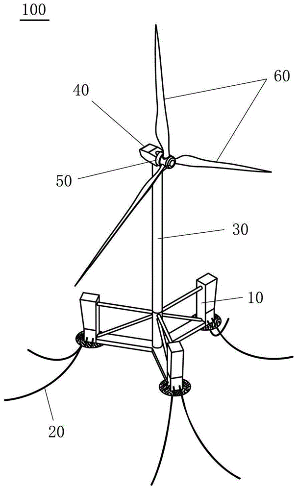
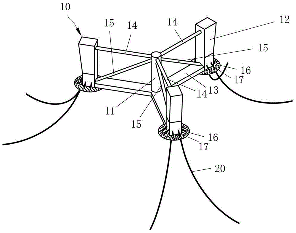
[0035] Such as figure 1 As shown, a floating wind turbine or floating wind turbine 100 according to an embodiment of the present invention includes a floating wind turbine foundation 10 , mooring cables 20 , tower 30 , nacelle 40 , wind turbine 50 and blades 60 . In the embodiment according to the present invention, the floating wind turbine foundation 10 is a semi-submersible floating wind turbine foundation. As the name implies, when the floating wind turbine 100 is installed on the sea surface, a part of the floating wind turbine foundation 10 will be submerged below the sea surface, and supported in this way The main body of the wind turbine, that is, the tower 30, the nacelle 40, the wind turbine 50, the blades 60, and the like. Since the floating wind turbine foundation 10 is able to move with sea waves, it is anchored to the seabed by mooring cables 20...


PUM


Abstract

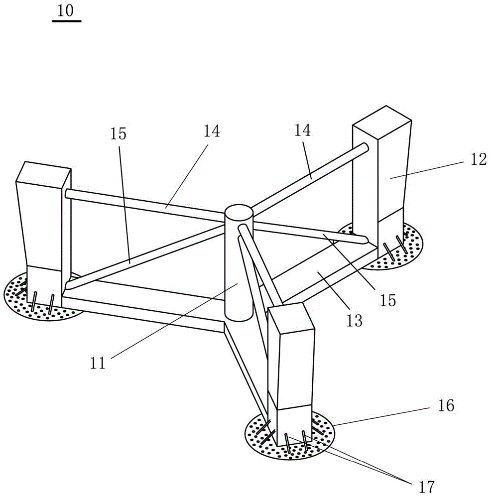
The invention provides a semi-submersible type floating fan base and a floating fan. The floating fan base comprises at least three stand columns, a stand column connecting structure and a supporting stand column, wherein the stand column connecting structure is connected with the lower ends of the stand columns to integrate the stand columns and the stand column connecting structure into a whole; the supporting stand column is arranged in the center of the floating fan base and used for supporting a tower, a cabin, blades and a wind generating system of the fan; and the cross sectional area of each stand column gradually grows large from a preset position underwater to top. The floating fan comprises the semi-submersible type floating fan base, the tower, the cabin, the wind generating system and the blades, wherein the tower is mounted on the supporting stand column of the semi-submersible type floating fan base; the cabin is mounted on the top of the tower; and the wind generating system and the blades are mounted at the front end of the cabin. According to the semi-submersible type floating fan base, the structure and the movement performance of the floating fan are improved, and production cost and installation cost are reduced.

Description

technical field [0001] The invention relates to the field of offshore wind power generators, more specifically, to a semi-submersible floating wind turbine foundation with improved structure and a floating wind turbine with the semi-submersible floating wind turbine foundation. Background technique [0002] In the deep sea area above 50 meters, there are more and better wind resources that can be developed and utilized, and the market prospect is also broader. To develop deep-sea wind farms in these sea areas, it will not be advantageous to fix the various through-pile structures on the seabed that are commonly used in offshore wind farms, because: as the water depth increases, the cost of fixed foundations rises linearly; fixed offshore wind turbines The cost of construction and operation and maintenance is higher than that of floating type. Therefore, in order to enable the construction of offshore wind farms to develop into deep sea areas, it is necessary to develop econ...

Claims


Application Information

Patent Timeline
IPC IPC(8): B63B35/44E02D27/42E02D27/52
CPCB63B1/107B63B2035/446B63B2039/067
Inventor 李荣富
Owner XINJIANG GOLDWIND SCI & TECH
Why Eureka
Eureka Blog
Learn More