

Heat exchanger pipeline galvanizing groove
A technology of galvanizing tank and heat exchanger, applied in hot-dip galvanizing process, coating, metal material coating process, etc., can solve the problems of liquid residue, affecting production efficiency, cleaning difficulties, etc., and achieve the same product processing effect , Avoid cleaning difficulties and facilitate post-processing effects
- Summary
- Abstract
- Description
- Claims
- Application Information
AI Technical Summary
Problems solved by technology
Method used
Image

Examples
Embodiment Construction
[0011] The technical solutions of the present invention will be further described below in conjunction with the accompanying drawings and through specific implementation methods.
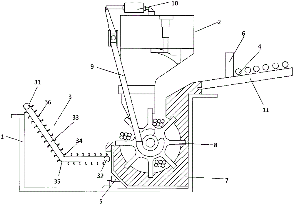
[0012] see figure 1 , in an embodiment of the present invention, a heat exchanger pipe galvanizing tank, including a tank body 1, a frame 2, a transmission device 3 and a toothed plate 8, and the frame 2, the transmission device 3 and the toothed plate 8 are arranged in the tank In the body 1, the toothed disc 8 is arranged under the frame 2, and a feeding guide rail 11 is arranged on the upper right side of the toothed disc 8. The feeding guide rail 11 is inclined at an angle of 20° to the horizontal plane, and the feeding guide rail 11 is provided with a control The gate 6 and the steel pipe 4 enter the tank body 1 through the control gate 6 along the feed guide rail 11 under the action of gravity. The control gate 6 controls the number of steel pipes entering each batch to be 6 pieces. The arc-s...
PUM
 Abstract
Description
Claims
Application Information