
Corrugated steel web plate-steel pipe concrete flange combined section T-shaped column

A corrugated steel web and concrete-filled steel tube technology, applied in columns, piers, pillars, etc., can solve the problems of limited shear bearing capacity, seismic performance and overall stability, increased overall project cost, and large connection workload. , to achieve the effect of superior overall stable bearing capacity, reduced comprehensive project cost and less steel consumption

Inactive Publication Date: 2015-03-11
NANJING UNIV OF TECH
View PDF7 Cites 1 Cited by
  • Summary
  • Abstract
  • Description
  • Claims
  • Application Information

AI Technical Summary

Problems solved by technology

If you choose a special-shaped steel column with flat web and solid web T-section, the shear strength of the web will be much more than that, but in order to ensure the local stability of the web, the web height-thickness ratio limit stipulated in the "Code for Design of Steel Structures" must be met. Value, usually need to increase its web thickness, which will lead to increased steel consumption, increased project cost, thereby increasing the overall cost of the project; In addition to the limited performance and overall stability, the truss-type web members need to be welded with plates or strips, the construction is relatively cumbersome, the connection workload is large, and the construction cost is increased, which also increases the overall cost of the project.
Moreover, when the bending moment effect is large, the flanges of the above two T-shaped special-shaped steel columns may enter the failure state prematurely, causing the steel columns to quickly lose their resistance; at the same time, the above two steel columns are all pure steel structure, its fire resistance is poor

Method used


Image

  • Corrugated steel web plate-steel pipe concrete flange combined section T-shaped column
  • Corrugated steel web plate-steel pipe concrete flange combined section T-shaped column

Examples


Embodiment Construction

[0024] The present invention will be further described below in conjunction with the accompanying drawings and specific embodiments.

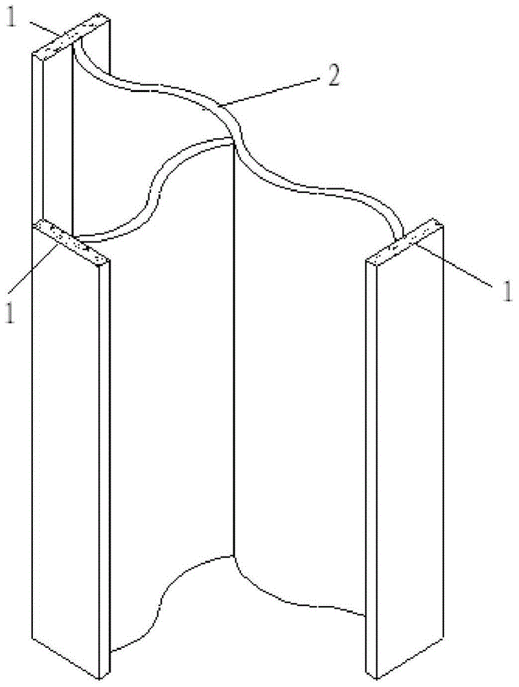
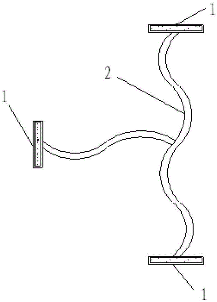
[0025] Such as figure 1 and 2 Shown: a corrugated steel web-concrete-filled steel tube flange composite section T-shaped column, which is composed of web H-shaped steel and web T-shaped steel welded, or composed of two webs and three flanges welded, the web The plate is a corrugated steel web 2, and the form of the corrugated steel column web 2 is curved, broken line or trapezoidal, and the corrugated steel web 2 has periodically repeated corrugated sides perpendicular to the length direction of the member, and the corrugated steel web 2 is non-corrugated The shape edge is welded at the middle point of the width of the flange, and the flange is a steel pipe concrete flange 1, and the steel pipe concrete flange includes a steel pipe and the concrete inside thereof, and the concrete is self-compacting concrete. The cross-section forms of the T-...


PUM


Abstract

The invention discloses a corrugated steel web plate-steel pipe concrete flange combined section T-shaped column which is formed through welding web plate H-shaped steel and web plate T-shaped steel or welding two web plates and three flanges, wherein web plates are corrugated steel web plates which are curvilinear, polygonal-shaped or trapezoid; the periodically repeated corrugated edges of the corrugated steel web plates are perpendicular to the length direction of a member; the non-corrugated edges of the corrugated steel web plates are respectively welded with the middle points in the width directions of the flanges; the flanges are steel pipe concrete flanges; the steel pipe concrete flanges comprise steel pipes and concrete in the steel pipes; the concrete is self-compacting concrete. According to the corrugated steel web plate-steel pipe concrete flange combined section T-shaped column, the stress performance of a conventional solid web type specially-shaped steel column and the stress performance of a truss type web member specially-shaped steel column are improved, and the comprehensive manufacturing cost of engineering is not obviously increased, so that a specially-shaped column structure can be widely applied to multiple high-rise buildings.

Description

technical field [0001] The invention relates to the technical field of a novel building structure, in particular to a T-shaped column with a combined section of a corrugated steel web and a steel tube concrete flange. Background technique [0002] In residential buildings, special-shaped column structures have incomparable advantages over other structural systems, and are more and more favored by people. In recent years, they have been highly valued by scholars and engineers at home and abroad, and thus have been widely used. [0003] However, in multi-story residential buildings, the reinforced concrete special-shaped column structure is difficult to meet the bearing capacity requirements due to the limitation of the length and thickness ratio of the column section, the crowded reinforcement in the node area, and the unsatisfactory seismic performance and difficult to deal with. The advantages of the special-shaped column cannot be fully reflected, thereby limiting its appl...

Claims


Application Information

Patent Timeline
IPC IPC(8): E04C3/36
Inventor 郑廷银郝佩佩顾郑扬
Owner NANJING UNIV OF TECH
Learn More