Stroke differential type high-energy hydraulic drive down-hole hammer

A down-the-hole impactor and differential technology, which is applied to the driving device for drilling in the borehole, drilling equipment, earthwork drilling and production, etc., can solve the problems of unfavorable high-energy continuous output, long overall axial dimension, and high processing accuracy requirements , to achieve the effects of improving drilling efficiency in hard rock, long service life, and high final impact velocity

Inactive Publication Date: 2015-03-11
JILIN UNIV
View PDF10 Cites 16 Cited by
  • Summary
  • Abstract
  • Description
  • Claims
  • Application Information

AI Technical Summary

Problems solved by technology

[0003] CN201420513172.4 discloses a "valve-type high-energy hydraulic down-the-hole hammer". The valve core uses moving steps to control the fluid, has many matching surfaces, requires high machining accuracy, and is easy to wear
And the spool does not have a buffer mechanism, the dead point of the spool travel is prone to damage and failure due to frequent rigid collisions, which is not conducive to high-energy continuous output
The piston is processed with multi-stage stepped surfaces, the overall axial dimension is long, there are many mating surfaces, the friction area is large, and the reliability is poor in the complex environment at the bottom of the well

Method used


Image

  • Stroke differential type high-energy hydraulic drive down-hole hammer
  • Stroke differential type high-energy hydraulic drive down-hole hammer
  • Stroke differential type high-energy hydraulic drive down-hole hammer

Examples


Embodiment Construction

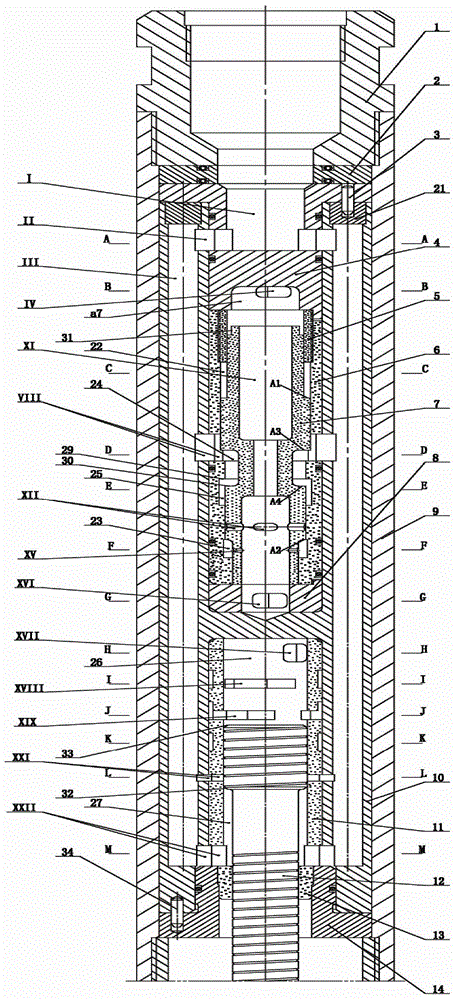
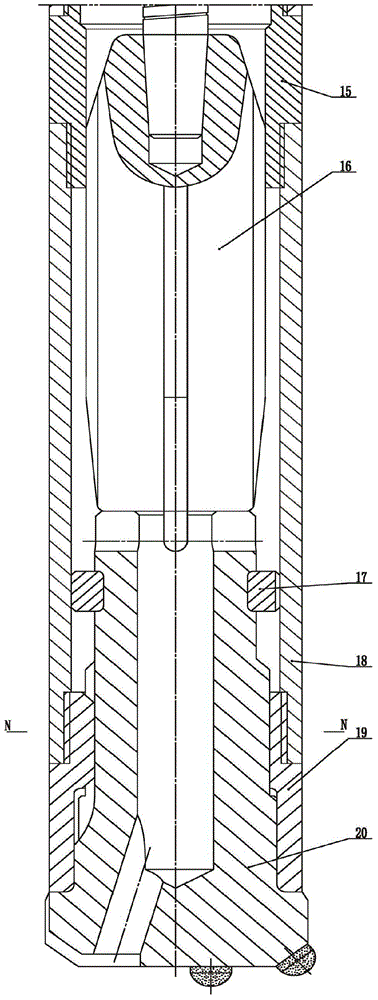
[0030] Below in conjunction with accompanying drawing and embodiment the present invention is described in further detail:

[0031]The stroke differential high-energy hydraulic down-the-hole impactor is a sliding fit between the spline on the drill bit 20 and the spline groove on the spline sleeve 19, the drill bit 20 slides in the axial direction, and aligns with the lower step of the drill bit 20 through the semicircular clamp 17. The drill bit 20 is limited to prevent the drill bit from slipping from the spline sleeve. The spline sleeve 19 is connected to the outer pipe 18 through threads, the outer pipe 18 is threaded to the middle joint 15, the middle joint 15 is connected to the outer cylinder 9 through threads, and the cylinder liner 11 The end cover sleeve 13 is fitted into the cylinder body 10 and the lower cylinder head 14 respectively by interference fit. The piston 12 is processed into two sections with different diameters to form a piston step surface 32. The entir...


PUM


Abstract

The invention relates to a stroke differential type high-energy hydraulic drive down-hole hammer. A spline on a drill bit is in sliding fit with a spline groove, a valve cover sleeve is in interference fit with a valve sleeve to be installed into the upper end of the valve sleeve. A valve cover is inserted into a cylinder body upper end hole and is radially provided with low-pressure emptying channels, hole channels corresponding to the radial channels are radially formed in the radial direction of a cylinder body and are communicated with axial hole channels. The upper portion of the high-energy hydraulic drive down-hole hammer is in threaded connection with an outer cylinder through an upper connector and a middle connector respectively to form a whole through package. The axial size of a piston of the hammer is small, matching surfaces are few, the leakage area is greatly decreased, and the hammer is easy to assemble, not prone to abrasion, long in service life and high in sensitivity. A differential loop is adopted for a stroke, so that the piston quickly obtains large impact end speed within a shorter stroke, and the hard rock drilling efficiency is remarkably improved. The hammer is provided with a novel empty hammering preventing mechanism, high-pressure slurry flows into a cavity through the channels and then flows into the bottom of a hole, the hammer is not driven, it is ensured that the down-hole hammer does not work when a drilling tool is lifted to be away from the down-hole hammer, and accordingly the safety of the drilling tool is ensured.

Description

Technical field: [0001] The invention relates to a drilling tool, in particular to a high-energy hydraulic down-the-hole impactor used for oil and gas drilling, mineral exploration and rapid drilling of hot dry rock. Background technique [0002] In various drilling projects, drilling efficiency is the main factor restricting the cost of various drilling projects. The use of high-efficiency drilling tools can greatly improve drilling efficiency in the process of drilling hard and broken formations, and effectively reduce drilling costs. Among the various existing drilling methods, the percussion rotary drilling process is considered to be the most efficient drilling method, and the pneumatic down-the-hole hammer is currently the most efficient DTH hammer drilling tool. However, due to its limited drilling depth Due to formation back pressure limitation, it can only be used for shallow hole drilling. Existing hydraulic down-the-hole impactors use drilling fluid as the power ...

Claims


Application Information

Patent Timeline
Patent Type & Authority Applications(China)
IPC IPC(8): E21B4/06
CPCE21B4/14
Inventor 彭枧明孙铭泽张鑫鑫孙强杨冬冬纪天坤博坤罗永江李鹏
Owner JILIN UNIV
Why Eureka
Try Eureka