Horizontal-motion float-type direct-drive wave energy device

A horizontal movement, float-type technology, applied in the direction of ocean energy power generation, engine components, machines/engines, etc., can solve problems such as low stability and poor safety

Inactive Publication Date: 2015-03-11
CHANGSHA UNIVERSITY OF SCIENCE AND TECHNOLOGY
View PDF6 Cites 9 Cited by
  • Summary
  • Abstract
  • Description
  • Claims
  • Application Information

AI Technical Summary

Problems solved by technology

[0004] The technical problem to be solved by the present invention is to overcome the low stability and poor safety of the above-mentioned existing wave energy technology, and provide a horizontally moving buoy type direct drive wave energy device, which can utilize the seawater flow rate generated by the wave transmission. Changes, e

Method used


Image

  • Horizontal-motion float-type direct-drive wave energy device
  • Horizontal-motion float-type direct-drive wave energy device
  • Horizontal-motion float-type direct-drive wave energy device

Examples


Embodiment 1

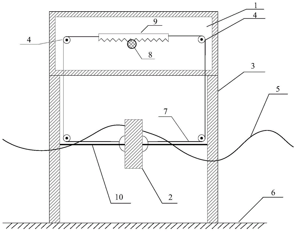
[0022] Such as figure 1 As shown, the device as a whole is placed on the seabed foundation 6 through the column 3; the power generation cabin 1 is installed above the column 3, and the gear box, the transmission rack 9 and the generator 14 are installed in the power generation cabin 1; the rail 10 is laid between the two columns 3 and the float 2; the two ends of the track 10 are respectively fixed on the column 3; the left and right sides of the float 2 are connected with steel cables 7 and connected with the transmission rack 9 through the fixed pulley 4; the transmission rack 9 and the gear box in the power generation cabin 1 The input rotating shaft 8 is occlusally connected; the two ends of the transmission rack 9 are hingedly connected with the steel cable 7 respectively.

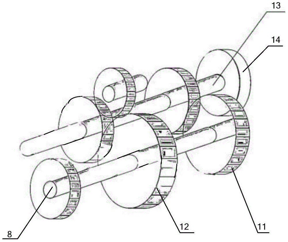
[0023] Such as figure 2 As shown, a set of clockwise ratchet mechanisms 11 and a set of counterclockwise ratchet mechanisms 12 are installed in the gearbox; the ratchet mechanisms in the gearbox are...


PUM


Abstract

The invention belongs to the field of novel renewable energy technologies and ocean equipment, and particularly relates to a horizontal-motion float-type direct-drive wave energy device. The horizontal-motion float-type direct-drive wave energy device comprises an electricity generation cabin, a float, stand columns, fixed pulleys, a steel cable, a gearbox, a rail and an electric generator. The device is characterized in that the device is wholly placed on a sea-floor foundation through the stand columns; the electricity generation cabin is installed on the stand columns; the gearbox, a transmission rack and the electric generator are installed in the electricity generation cabin; the rail and the float are arranged between the two stand columns, and the two ends of the rail are fixed to the stand columns respectively; and the float is connected with the transmission rack through the steel cable and the fixed pulleys. The horizontal-motion float-type direct-drive wave energy device is suitable for offshore areas with rich wave energy resources; the design that the horizontal motion of the float of the float-type direct-drive wave energy device is adopted, and therefore the device can adapt to waves in different sizes. The electricity generation principle is simple, and efficiency is stable. An electricity generation device is arranged inside a device body, and safety is high; and the overall float-type direct-drive wave energy device is simple in form and convenient to manufacture and mount.

Description

technical field [0001] The invention belongs to the field of novel renewable energy technology and marine equipment, in particular to a horizontally moving floater type direct drive wave energy device. Background technique [0002] With the development of the world economy, the increase of population, and the continuous improvement of social living standards, the demand for energy in various countries is growing rapidly. In recent years, driven by the depletion of fossil energy, energy supply security, and environmental protection, ocean energy, one of the major renewable energy sources, has made great progress, and ocean energy application technologies have become increasingly mature, providing human beings with the opportunity to make full use of ocean energy in the 21st century. A bright future is shown. [0003] At present, the main wave energy devices in the world can be divided into three categories according to their location distribution: offshore type (more than 2....

Claims


Application Information

Patent Timeline
IPC IPC(8): F03B13/16
CPCY02E10/30
Inventor 彭伟
Owner CHANGSHA UNIVERSITY OF SCIENCE AND TECHNOLOGY
Why Eureka
Try Eureka