Tube fin type cooler based on thermal medium flow rate

A heat medium, tube-fin technology, applied in indirect heat exchangers, heat exchanger types, tubular elements, etc., can solve the problems of high heat dissipation requirements, low fin density and form requirements, and waste of heat exchange capacity. Simple processing technology, low cost of use, and the effect of ensuring heat transfer performance

Inactive Publication Date: 2015-03-11
ZHEJIANG UNIV
View PDF4 Cites 1 Cited by
  • Summary
  • Abstract
  • Description
  • Claims
  • Application Information

AI Technical Summary

Problems solved by technology

In this case, for radiators with evenly distributed fins, there must be a waste of heat exchange capacity: for flat tubes with high flow rate, the heat dissipation requirements are relatively high, and fins with larger heat dissipation coefficients need to be used; and Lower requirements on fin density and form through flat tubes with extremely low flow rates
Evenly distributed dense fins are uniformly used, although it can ensure heat dissipation, it will also generate redundant resistance energy consumption

Method used


Image

  • Tube fin type cooler based on thermal medium flow rate
  • Tube fin type cooler based on thermal medium flow rate
  • Tube fin type cooler based on thermal medium flow rate

Examples


Embodiment Construction

[0024] The present invention will be further described below in conjunction with the accompanying drawings of the description.

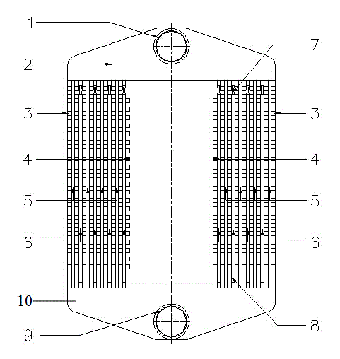
[0025] According to the simulation calculation, it is found that due to the influence of the structure of the radiator head, the flow rate and corresponding pressure in each channel of the radiator are quite different. Figure 9 It is the pressure difference curve between the channels of the common structure intercooler under different working conditions, where Case9 corresponds to the working condition with a larger heat medium flow rate. Depend on Figure 9 It can be seen that under the condition that the overall flow rate of the heat medium is large, the difference in pressure difference between the channels reaches several thousand Pa. Even under the condition of small flow rate, the difference of pressure difference is close to 400Pa. In the channel with higher flow, the pressure may reach more than 2000 Pa. For liquid-gas heat exchange radia...


PUM


Abstract

The invention discloses a tube fin type cooler based on a thermal medium flow rate. The tube fin type cooler comprises a medium inlet, a head connecting pipe, fins which are in the shape of a Chinese word of ''Bow'', a fixed pipe, a movable pipe and the like, wherein the two ends of the fixed pipe are respectively connected with the head connecting pipe and a tail part connecting pipe; the upper and lower ends of the movable pipe are respectively connected with the head connecting pipe and the tail part connecting part by telescopic segments; the fixed pipe and the movable pipe are sequentially and alternately arranged; each telescopic segment is made from an elastic plastic material; an upper telescopic segment of the movable pipe is in a compressed state; the fins are a plurality of structures which are connected in series and in the shape of Chinese word of ''Bow'', and are arranged and mounted in parallel between the fixed pipe and the movable pipe; two adjacent fins are respectively fixed together with the fixed pipe and the movable pipe; the distribution mode of the fins can be regulated according to the flow rate of a thermal medium (hot oil or water). Staggered fins with a higher cooling efficient are formed close to a high-flow tube, and flat and straight fins are retained close to a low-flow tube so that energy consumption caused by resistance is reasonably reduced, and the work efficiency of the cooler is improved.

Description

technical field [0001] The invention relates to a heat transfer device, in particular to a tube-fin radiator based on heat medium flow. Background technique [0002] The tube-fin radiator is a common compact radiator. Its core is composed of flat tubes and fins welded on the flat tubes. Because of its high efficiency, compactness and lightness, it is widely used as a vehicle-mounted water tank. and various oil radiators. For this kind of compact tube-fin radiator, since the flat tube structure is relatively simple, the fin form plays a key decisive role in the heat transfer and resistance performance of the entire radiator. Common fin forms include staggered, louvered, corrugated, perforated, straight and so on. Studies have shown that compared with straight fins, the use of staggered fins can lead to a higher heat transfer coefficient, but at the same time, the drag coefficient will also be greatly increased, thereby amplifying the overall resistance of the cooling system...

Claims


Application Information

Patent Timeline
IPC IPC(8): F28D1/053F28F1/12
Inventor 黄钰期俞小莉黄瑞李慧洁
Owner ZHEJIANG UNIV
Why Eureka
Try Eureka