Pedestrian navigation device and pedestrian navigation method based on inertial sensor

An inertial sensor, pedestrian navigation technology, applied in navigation, navigation through speed/acceleration measurement, measurement device and other directions, can solve the problem that the pedometer cannot distinguish different step states, cannot navigate, and the algorithm accuracy is not very high.

Active Publication Date: 2015-03-11
JIANGSU TOYOU RES INST OF INFORMATION INTELLIGENCE & TECH
View PDF2 Cites 36 Cited by
  • Summary
  • Abstract
  • Description
  • Claims
  • Application Information

AI Technical Summary

Problems solved by technology

However, the inertial navigation system itself has many shortcomings. The most serious error is that the error will accumulate over time. For example, when using a gyroscope to measure angular velocity, due to some characteristics of the gyroscope itself, there are phenomena such as zero point drift, so it is necessary to use various Algorithms to continuously correct and process to eliminate cumulative errors
And due to the limitation of accuracy, general commercial gyroscope sensors cannot measure a wide range of angular velocity values, and when pedestrians are walking or even going up and down stairs, the instantaneous angular velocity value will be much larger than its range
[0003] At present, some scholars have researched the MEMS-based inertial navigation system. In order to overcome the shortcomings of the system itself and improve the accuracy of the system, some researchers used a pedometer to count the number of steps, and then calculated the number of steps based on this statistics. The average step length can calculate and estimate the walking distance and trajectory, but the pedometer cannot dist

Method used


Image

  • Pedestrian navigation device and pedestrian navigation method based on inertial sensor
  • Pedestrian navigation device and pedestrian navigation method based on inertial sensor
  • Pedestrian navigation device and pedestrian navigation method based on inertial sensor

Examples


Embodiment Construction

[0053] The technical solutions of the present invention will be described in detail below in conjunction with the accompanying drawings.

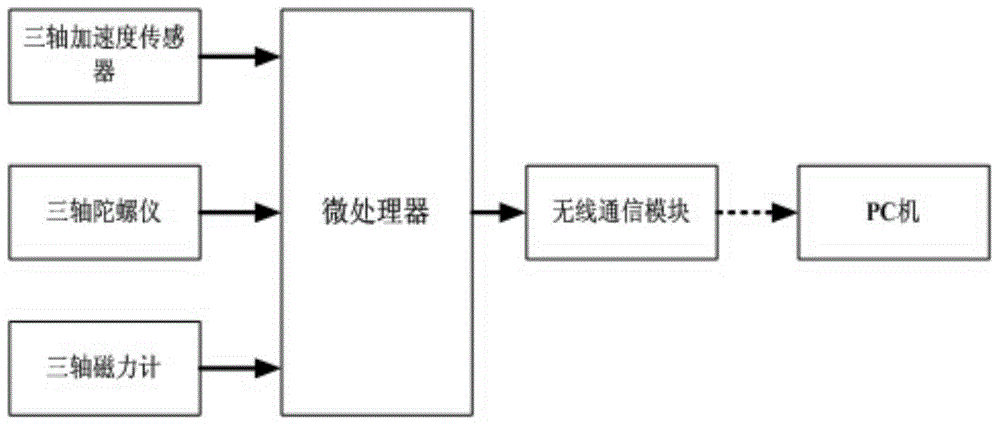
[0054] Such as figure 1 Shown is the system structure block diagram of the present invention, the pedestrian navigation device based on the inertial sensor, including a microprocessor and a three-axis acceleration sensor, a three-axis gyroscope, a three-axis magnetometer and a wireless communication module respectively connected thereto, the microprocessor The device receives the data collected by the three-axis acceleration sensor, the three-axis gyroscope and the three-axis magnetometer, and uploads these data to the PC through the wireless communication module. In this embodiment, the three-axis acceleration sensor adopts the MMA7361 of Freescale Company, the three-axis gyroscope adopts the 500 series of InvenSense Company, the three-axis magnetometer adopts the HMC5842 of Honeywell Company, and the wireless communication module adopts t...


PUM


Abstract

The invention discloses a pedestrian navigation device based on an inertial sensor. The pedestrian navigation device comprises a microprocessor, a three-axis acceleration sensor, a three-axis gyroscope, a three-axis magnetometer and a wireless communication module, wherein the three-axis acceleration sensor, the three-axis gyroscope, the three-axis magnetometer and the wireless communication module are respectively connected with the microprocessor; the microprocessor is used for receiving data collected by the three-axis acceleration sensor, the three-axis gyroscope and the three-axis magnetometer and uploading the data to a PC (Personal Computer) through the wireless communication module. The invention further discloses a pedestrian navigation method based on the pedestrian navigation device. The pedestrian navigation method comprises a step stage detection algorithm, a foot and body orientation estimation algorithm and an extended Kalman filter algorithm. The complexity of calculation is greatly reduced while the accuracy is guaranteed, and a condition that the requirement of timeliness can be met is guaranteed without consuming a large amount of hardware power consumption in a practical environment.

Description

technical field [0001] The invention belongs to the technical field of navigation, and in particular relates to a pedestrian navigation device and method based on an inertial sensor. Background technique [0002] With the rapid growth of data services and multimedia service data, the demand for high-precision pedestrian navigation systems is increasing day by day. People with such navigation systems can easily enjoy many location-based services (Location-Based Services, LBS). However, due to the impact of the urban jungle environment, the GPS signal will be blocked or reflected by skyscrapers to a large extent, resulting in the inability to locate and navigate directly through GPS. Therefore, based on the low-cost Micro Electro-Mechanic System (Micro Electro-Mechanic System , MEMS) solutions have gradually entered people's sight. The pedestrian inertial navigation system based on MEMS uses a set of inertial sensors included in itself, such as acceleration sensors, gyroscope...

Claims


Application Information

Patent Timeline
IPC IPC(8): G01C21/16
CPCG01C21/165
Inventor 周亮周暄承陈建新王磊魏昕董义薛雯苏宇
Owner JIANGSU TOYOU RES INST OF INFORMATION INTELLIGENCE & TECH
Why Eureka
Try Eureka