Optical system for measuring retro-reflecting coefficient
A retroreflection coefficient and optical system technology, applied in the measurement of scattering characteristics, etc., can solve the problems of cumbersome test process, low test accuracy, and bulky volume, and achieve the effects of variable incident angle and observation angle, convenient operation, and small size
- Summary
- Abstract
- Description
- Claims
- Application Information
AI Technical Summary
Problems solved by technology
Method used
Image
Examples
Embodiment Construction
[0032] The present invention will be further described below in conjunction with accompanying drawing:
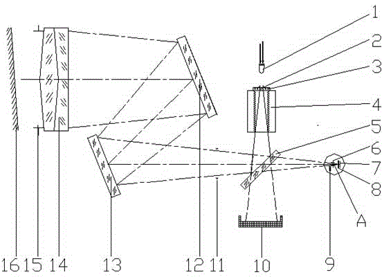
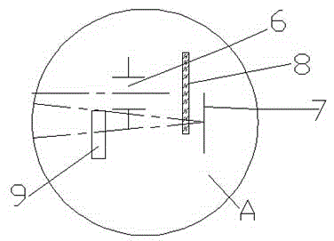
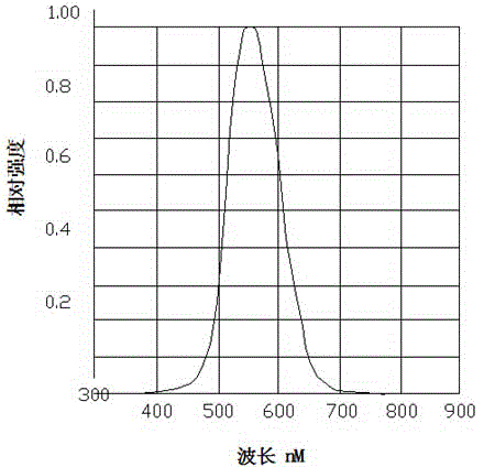
[0033] Such as Figure 1-Figure 2 The shown optical system for measuring the retroreflection coefficient includes an illumination light source, a beam splitter 5 , a mirror, an achromatic objective lens 14 , a filter 8 and a photodiode receiver 7 . The beam splitter 5 is arranged obliquely at an angle of 45 degrees below the illumination source. The reflector, the achromatic objective lens 14 , the optical filter 8 and the photodiode receiver 7 are arranged on the left and right sides of the illumination light source and the beam splitter 5 respectively. A stray light absorbing device 10 is arranged below the beam splitter 5 . Preferably, the achromatic objective lens 14 is a double-bonded achromatic objective lens with a medium focal length. The filter 8 is a vision correction filter, which corrects the visual curve. The photodiode receiver 7 is a silicon photodiode re...
PUM
 Abstract
Description
Claims
Application Information
 - R&D
- Intellectual Property
- Life Sciences
- Materials
- Tech Scout
- Unparalleled Data Quality
- Higher Quality Content
- 60% Fewer Hallucinations
Browse by: Latest US Patents, China's latest patents, Technical Efficacy Thesaurus, Application Domain, Technology Topic, Popular Technical Reports.
© 2025 PatSnap. All rights reserved.Legal|Privacy policy|Modern Slavery Act Transparency Statement|Sitemap|About US| Contact US: help@patsnap.com


