
Indoor positioning method based on bidirectional wireless optical communication

A wireless optical communication, indoor positioning technology, applied in the field of positioning, can solve the problems of complex equipment, low positioning accuracy of a single lamp, limited transmission distance, etc., and achieve the effect of simplifying the design and difficulty

Active Publication Date: 2015-03-11
ACAD OF OPTO ELECTRONICS CHINESE ACAD OF SCI
View PDF3 Cites 23 Cited by
  • Summary
  • Abstract
  • Description
  • Claims
  • Application Information

AI Technical Summary

Problems solved by technology

[0013] In the process of realizing the present invention, the applicant found that the existing indoor positioning method has the following technical defects: the positioning accuracy of a single light is low; positioning based on the signal arrival angle is limited to a two-dimensional plane; positioning based on the relationship between light intensity and distance The transmission distance is limited; the photogrammetry positioning based on multiple PD arrays is relatively complicated

Method used


Image

  • Indoor positioning method based on bidirectional wireless optical communication
  • Indoor positioning method based on bidirectional wireless optical communication
  • Indoor positioning method based on bidirectional wireless optical communication

Examples


Embodiment Construction

[0032] In order to make the object, technical solution and advantages of the present invention clearer, the present invention will be described in further detail below in conjunction with specific embodiments and with reference to the accompanying drawings. It should be noted that, in the drawings or descriptions of the specification, similar or identical parts all use the same figure numbers. Implementations not shown or described in the accompanying drawings are forms known to those of ordinary skill in the art. Additionally, while illustrations of parameters including particular values ​​may be provided herein, it should be understood that the parameters need not be exactly equal to the corresponding values, but rather may approximate the corresponding values ​​within acceptable error margins or design constraints. The directional terms mentioned in the embodiments, such as "upper", "lower", "front", "rear", "left", "right", etc., are only referring to the directions of the...


PUM


Abstract

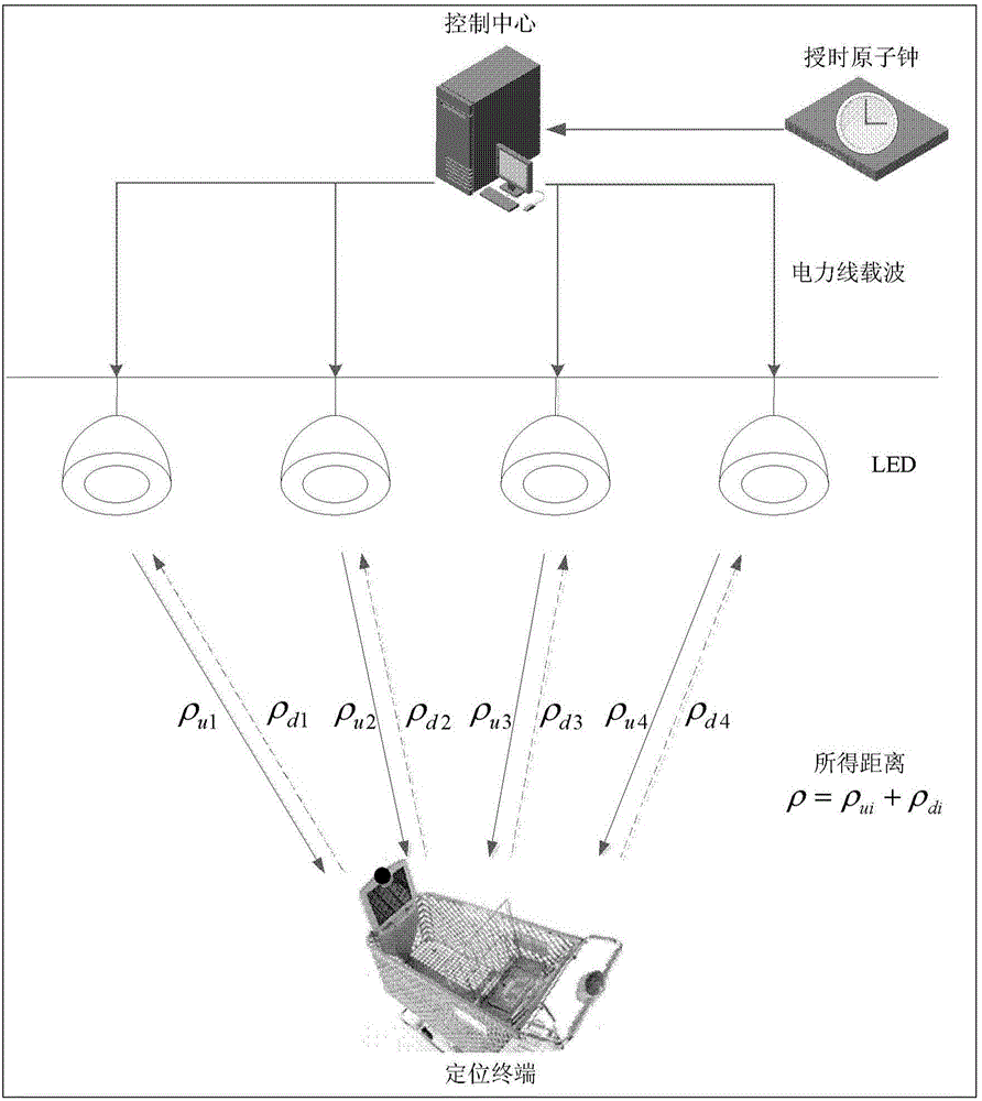
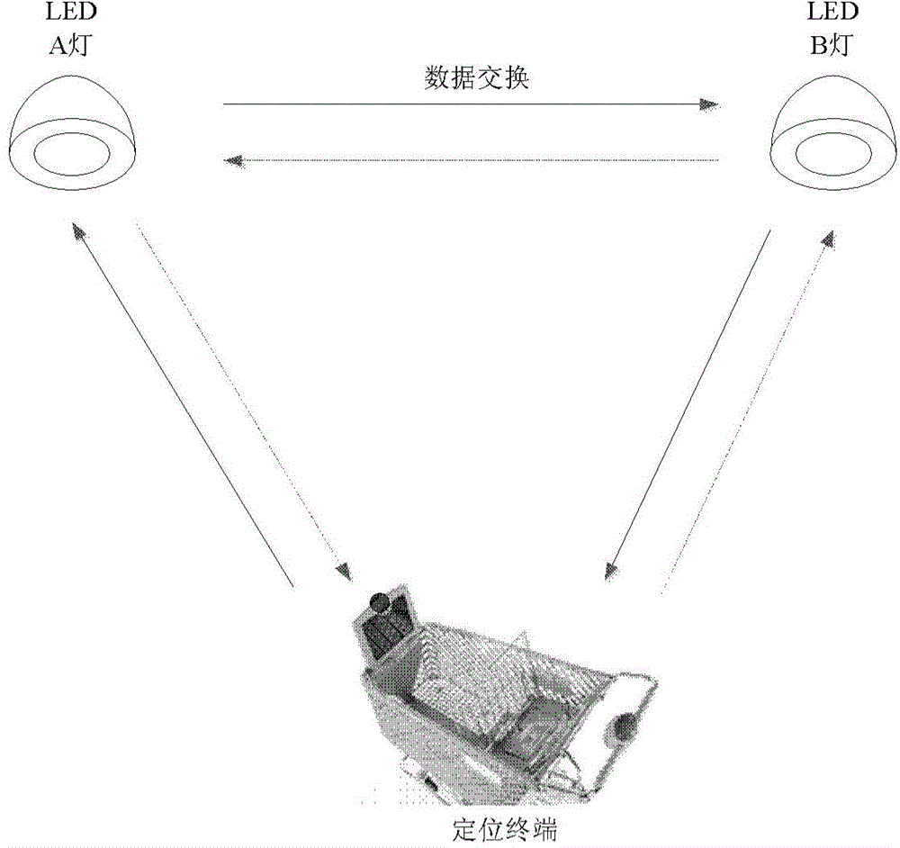
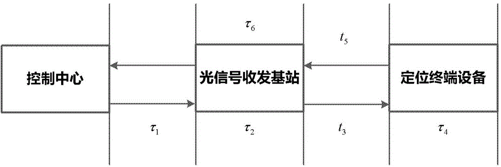
The invention provides an indoor positioning method based on a bidirectional wireless optical communication. The indoor positioning method comprises the steps: a control centre provides a uniform time reference to realize time synchronization of N optical signal transceiver base stations; the control centre sends a distance measurement signal to the N optical signal transceiver base stations; after receiving the distance measurement signal, the N optical signal transceiver base stations transmit signals within the coverage scope; an optical signal transponder on a positioning terminal answers emission signals of M optical signal transceiver base stations and sends answering signals to the corresponding optical signal transceiver base stations, in which the number M is not less than 3 and not more than N; the M optical signal transceiver base stations respectively transfer the received answering signals to the control centre; and the control centre determines the position of the positioning terminal according to a transfer and distance-measurement principle, the sending time of the distance measurement signal, the position information of the M optical signal transceiver base stations and the receiving time of the corresponding M answering signals. The function of the positioning terminal is simplified and the precision of the indoor position is improved.

Description

technical field [0001] The invention relates to the field of positioning technology, in particular to an indoor positioning method based on two-way wireless optical communication. Background technique [0002] At present, several typical ideas in the research of indoor positioning technology based on LED communication at home and abroad are as follows: [0003] (1) Single lamp positioning method based on LED-ID [0004] This method uses LED lights as beacons, and each light has a fixed ID. The LED lamp encodes its own ID information, adopts the OOK (binary open-close keying) signal modulation method, and continuously sends information to the outside. The positioning terminal determines the position of the positioning terminal based on the ID information in the LED communication information and the coverage of the corresponding LED. . [0005] (2) Positioning algorithm based on signal arrival angle [0006] First, assuming the vertical distances at the spread points are t...

Claims


Application Information

Patent Timeline
Patent Type & Authority Applications(China)
IPC IPC(8): G01S5/16
CPCG01S5/16
Inventor 巩应奎王语琪李延坤万红霞
Owner ACAD OF OPTO ELECTRONICS CHINESE ACAD OF SCI
Learn More