Kinetic energy recovery controller for electric vehicle

A kinetic energy recovery, electric vehicle technology, applied in electric vehicles, current collectors, vehicle components, etc., can solve the problems of inconvenient promotion and application, complex design, large size, etc., to improve safety and practicability, complete functions, and improve battery life. The effect of mileage

Active Publication Date: 2015-03-11
华贻科技(深圳)有限公司
View PDF5 Cites 2 Cited by
  • Summary
  • Abstract
  • Description
  • Claims
  • Application Information

AI Technical Summary

Problems solved by technology

The disadvantages of these solutions are that the product is heavy and bulky, or the power consumption is hig

Method used


Image

  • Kinetic energy recovery controller for electric vehicle
  • Kinetic energy recovery controller for electric vehicle
  • Kinetic energy recovery controller for electric vehicle

Examples


Embodiment 1

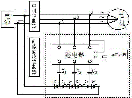
[0034] see figure 1 , this embodiment 1 discloses a kinetic energy recovery controller for an electric vehicle, including a control switch circuit, a start-stop switch, a capacitor circuit, a three-phase bridge rectifier circuit and a DC bridge series boost circuit, the kinetic energy recovery controller and the motor control The three output lines are connected in parallel to the three output lines of the motor stator. The three output lines output the A, B, and C three-phase AC kinetic energy converted by the motor when the vehicle is coasting. The control switch is an AC solid state relay. Resistance-capacity current limiting, and then three-phase bridge rectification, that is, the three capacitors C1, C2, and C3 are connected in series with the relay to the three-phase AC kinetic energy of A, B, and C, and then the AC of the three-phase bridge rectifier circuit The input terminal is connected to the three-phase AC kinetic energy of A, B, C, that is, three output lines,...

Embodiment 2

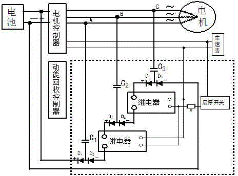
[0044] see figure 2 , figure 2 and figure 1 basically the same. The difference lies in the control switching circuit and the control switching power supply circuit, figure 1 It adopts AC relay and is installed at the AC input end of the three-phase bridge rectifier circuit, which is used to control the three-phase or any two-phase switch of the three-phase kinetic energy of A, B, and C; figure 2 It adopts a DC type relay, which is installed at the DC end of a three-phase bridge rectifier circuit, and is used as a switch to control the two series connection points in the middle of the DC bridge series boost circuit. Both circuits can realize switch control of kinetic energy recovery.

[0045] figure 1 The control switching power supply adopts the controlled dynamically changing kinetic energy itself, and its control circuit is connected to the main circuit of the controlled kinetic energy, that is, it is connected to any two of the three output lines; figure 2 The cont...

Embodiment 3

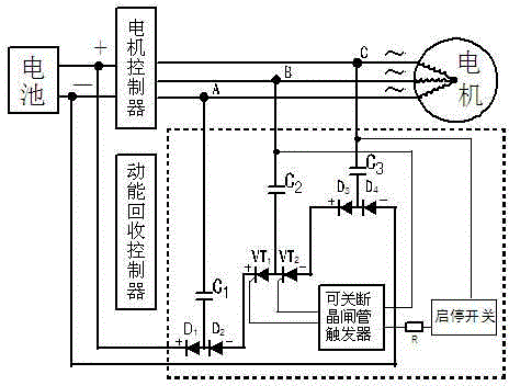
[0047] see image 3 , image 3 andfigure 1 basically the same. The difference is the controller switch circuit, figure 2 It adopts a DC relay, which is installed at the DC end of the three-phase bridge rectifier circuit, and is used as a switch to control the two series connection points in the middle of the DC bridge series boost circuit. image 3 The switchable thyristor is used as the rectifier and controllable switch of the middle B-phase bridge, and the switch of the rectifier of the B-phase bridge is controlled by the trigger of the turn-off thyristor. Both circuits can realize the switch control of kinetic energy recovery.


PUM


Abstract

The invention provides a kinetic energy recovery controller for an electric vehicle, and belongs to the technical field of energy recovery of the electric vehicle. The controller and a motor controller are jointly connected in parallel onto three output wires of a motor stator; a start-stop switch is mounted on a speed regulating assembly of the electric vehicle; during freewheeling, kinetic energy of the vehicle is converted into three-phase alternating current electric energy through the motor; and the controller can automatically select and recover gliding kinetic energy produced when the vehicle speed is close to or exceeds the average moving speed per hour in the city, capacitors are connected in series firstly, three-phase bridge rectification and direct current bridge type series connection boosting are performed, and the energy is fed back to batteries for storage finally. The kinetic energy recovery controller is characterized in that: 1), a control switch power supply adopts kinetic energy power; 2), a three-phase bridge rectification and direct current bridge type series connection circuit is adopted to design kinetic energy rectification and kinetic energy boosting; and 3), the capacitors are adopted to design kinetic energy recovery degree. The controller has simple design and comes onto the market in an embedded module manner, a safe and energy-saving mode is provided for medium-and-high-speed gliding of the electric vehicle in gear, the safety factor and the control performance of the electric vehicle can be improved, and the endurance mileage of the electric vehicle can be increased by about 20%.

Description

technical field [0001] The invention relates to a vehicle kinetic energy recovery device for an electric vehicle coasting, in particular to a kinetic energy recovery controller for an electric vehicle capable of solving kinetic energy boosting, kinetic energy rectification, kinetic energy recovery strength, and selective recovery and automatic control of kinetic energy. Background technique [0002] New energy electric vehicles have attracted widespread attention due to their advantages such as low cost of use and environmental protection. Due to the short cruising range, inconvenient use has become the biggest bottleneck. Under the condition that the battery technology is insurmountable, it is imperative to find other ways to increase the cruising range. [0003] At present, for domestic low-end electric vehicles, especially electric bicycles, the recovery of vehicle sliding kinetic energy seems to have not attracted the attention of manufacturers, and it is almost blank i...

Claims


Application Information

Patent Timeline
IPC IPC(8): H02J7/14
CPCY02T10/92H02J7/1492H02J7/345
Inventor 王继红
Owner 华贻科技(深圳)有限公司
Why Eureka
Try Eureka