Method for cooling heating element and recovering energy of heating element

A heating element and energy technology, applied in the electronic field, can solve the problems of large heat sink space, small size, low efficiency, etc., and achieve the effect of extending battery life

Inactive Publication Date: 2015-03-11
SUN YAT SEN UNIV
View PDF4 Cites 5 Cited by
  • Summary
  • Abstract
  • Description
  • Claims
  • Application Information

AI Technical Summary

Problems solved by technology

[0002] At present, the heating chips of electronic equipment such as computers are mainly cooled by cooling fins, fans, water cooling, and semiconductor cooling elements. The heat sink requires a large space for heat dissipation and has low efficiency. Other cooling methods need to consume electric energy. It is not suitable for cooling the heating chips of portable electronic devices such as mobile phones and tablets, because it will reduce battery life
[0003] Portable elect

Method used


Image

  • Method for cooling heating element and recovering energy of heating element
  • Method for cooling heating element and recovering energy of heating element
  • Method for cooling heating element and recovering energy of heating element

Examples


Embodiment 1

[0019] The following experiment will illustrate that the present invention actively cools the heating element and recycles the energy to verify that the present invention does not need to consume electric energy to actively cool the heating element, and convert heat energy into electrical energy to charge the battery during the cooling process. , to recover energy, the greater the work done by thermoelectric materials or thermoelectric devices, the more heat absorbed from the heating element. Advantages:

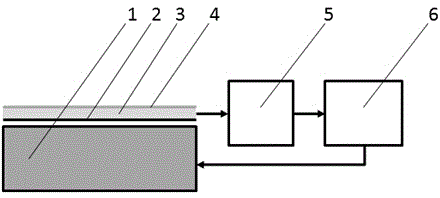
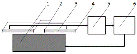
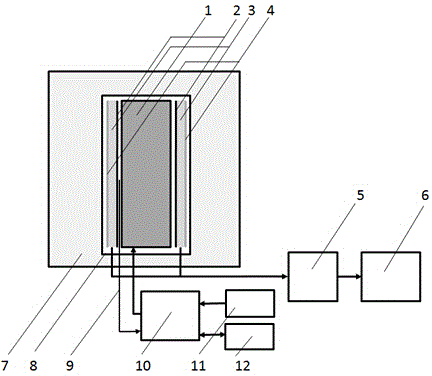
[0020] Such as image 3 As shown, it is a schematic structural diagram of an embodiment of the present invention, including a heating element 1, a high temperature end 2 of a thermoelectric device, a thermoelectric device 3, a low temperature end 4 of a thermoelectric device, a voltage stabilizing module 5, a rechargeable battery 6, and a constant temperature water bath 7 , a sealing film 8, a thermocouple 9, an intelligent temperature controller 10, a 220 volt AC power supp...

Embodiment 2

[0025] Embodiment 2 adopts the structural diagram in Embodiment 1 of the present invention (such as image 3 As shown), only the temperature control method of the heating element 1 by the intelligent temperature controller 10 is changed.

[0026] The temperature of the heating element 1 is kept constant at 75.0°C by the intelligent temperature controller 10, and the heating power percentage output by the intelligent temperature controller 10 to the heating element 1 is measured. In the measurement process, firstly, the thermoelectric circuit is opened for about 10 minutes, and the thermoelectric device 3 does not perform work; then the thermoelectric circuit is closed for about 10 minutes, and the thermoelectric device 3 performs work, and the current of the thermoelectric circuit is measured; then, the thermoelectric circuit is opened for about 10 minutes, and the thermoelectric device 3 No work is done; when the obtained heating element is at a constant temperature of 75.0°C...


PUM


Abstract

The invention relates to a method for cooling a heating element and recovering the energy of the heating element. According to the method, a thermoelectric material or a thermoelectric device on the surface of the heating element is used as a working substance, the temperature difference of the heating element and the environment is used to generate power and do work, the heat is absorbed from the heating element and is released to the surrounding environment through Carnot cycle, a voltage stabilizing module is connected to charge a power supply, so that the purposes of reducing the temperature of the heating element and recovering the energy of the heating element are fulfilled. The heating element is actively cooled without consuming electric power, the heat energy is converted to the electric power to charge the power supply in the cooling process, and the energy is recovered.

Description

technical field [0001] The invention relates to the field of electronic technology, and more specifically, relates to a method for cooling a heating body and recovering energy from the heating body by using electronic technology. Background technique [0002] At present, the heating chips of electronic equipment such as computers are mainly cooled by cooling fins, fans, water cooling, and semiconductor cooling elements. The heat sink requires a large space for heat dissipation and has low efficiency. Other cooling methods need to consume electric energy. It is not suitable for cooling the heating chips of portable electronic devices such as mobile phones and tablet computers, because it will reduce battery life. [0003] Portable electronic devices such as mobile phones and tablet computers are small in size, and the heat-generating chips mainly rely on the casing for heat dissipation. This is a form of passive cooling, and the heat dissipation efficiency is low. The heat g...

Claims


Application Information

Patent Timeline
IPC IPC(8): H02J7/32H02N11/00
CPCH02J7/32H02N11/002Y02B40/00
Inventor 林国淙丁喜冬
Owner SUN YAT SEN UNIV
Why Eureka
Try Eureka