
Surface mounting machine picking device suitable for multi-specification chips

A pick-up device and placement machine technology, which is applied to the assembly of printed circuits, printed circuits, and electrical components with electrical components, can solve problems such as poor chip size adaptability, reduced production efficiency, and inconvenient operation, so as to ensure smoothness and accuracy , the effect of improving work efficiency

Active Publication Date: 2015-03-11
HUAZHONG UNIV OF SCI & TECH
View PDF8 Cites 8 Cited by
  • Summary
  • Abstract
  • Description
  • Claims
  • Application Information

AI Technical Summary

Problems solved by technology

[0003] However, the adaptability of the suction nozzle to the chip size in the existing surface mounter is very poor, and the suction nozzle can only be adapted to chips in a specific specification or a smaller size range. When the picked-up object (for example, a chip) changes, Nozzle needs to be replaced, resulting in reduced productivity and great inconvenience in operation
For example, CN03230777.2 discloses a suction nozzle device, in which when the sucking object is changed to a large-size and high-quality chip, it is necessary to replace a large-diameter rubber suction nozzle in order to generate sufficient suction; another example, CN200620023171.7 discloses an array placement head, but when picking up and transferring various objects, it also needs to replace the rubber nozzles, which will bring troubles in storing, managing and maintaining different types of rubber nozzles

Method used


Image

  • Surface mounting machine picking device suitable for multi-specification chips
  • Surface mounting machine picking device suitable for multi-specification chips
  • Surface mounting machine picking device suitable for multi-specification chips

Examples


Embodiment Construction

[0034] In order to make the object, technical solution and advantages of the present invention clearer, the present invention will be further described in detail below in conjunction with the accompanying drawings and embodiments. It should be understood that the specific embodiments described here are only used to explain the present invention, not to limit the present invention. In addition, the technical features involved in the various embodiments of the present invention described below can be combined with each other as long as they do not constitute a conflict with each other.

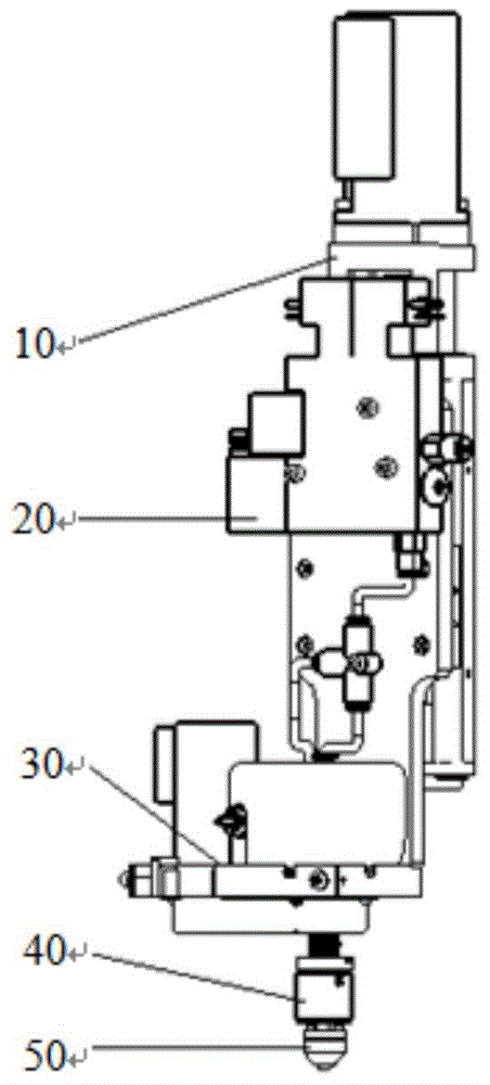
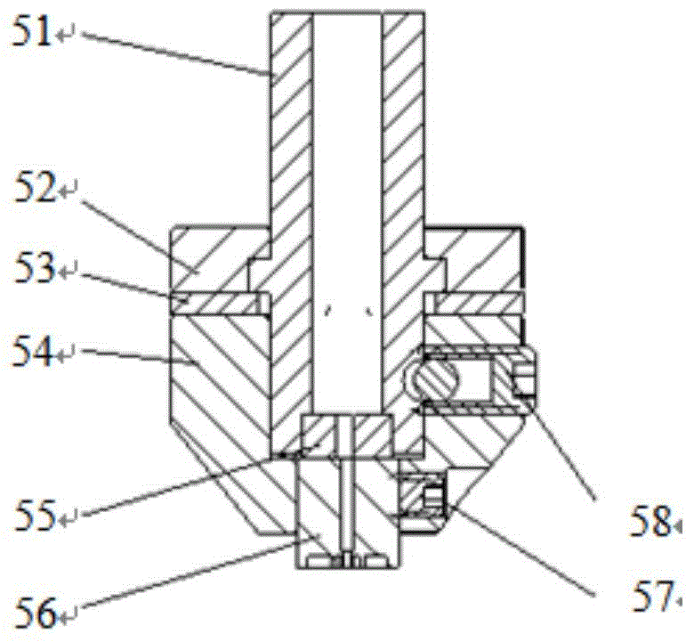
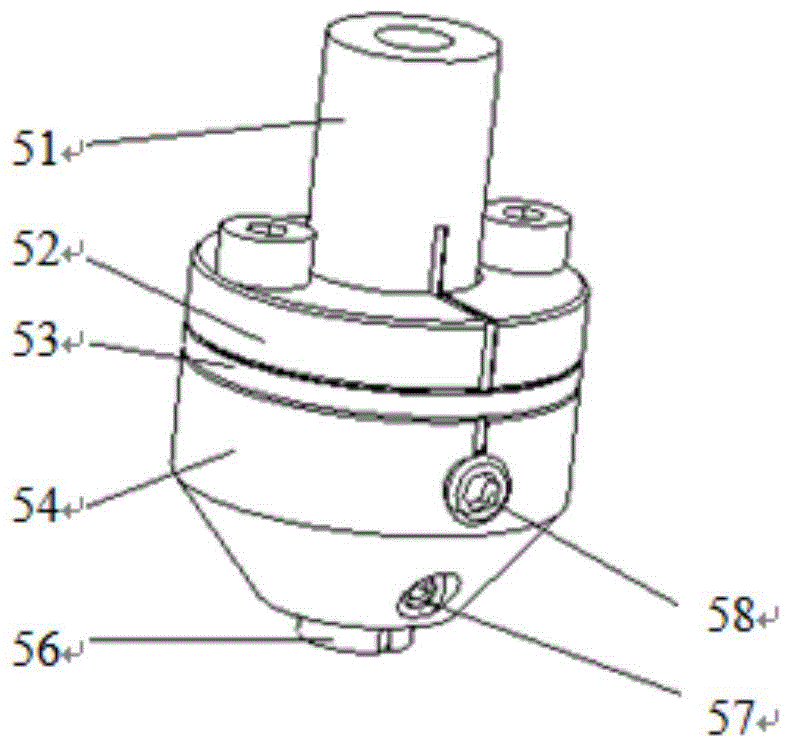
[0035] figure 1 is a schematic diagram of the overall structure of the pick-up device according to a preferred embodiment of the present invention. Such as figure 1 As shown in , the pick-up device mainly includes Z-direction feed module 10, transmission module 30, air circuit module 20, spline shaft module 40, suction nozzle module 50 and other components, which will be explained and illustra...


PUM


Abstract

The invention discloses a surface mounting machine picking device suitable for multi-specification chips. The surface mounting machine picking device comprises a Z-direction feeding module, a transmission module, an air passage module, a spline shaft module and a nozzle module, wherein the Z-direction feeding module is used for driving a back board to move up and down, a vacuum generator in the air passage module is used for generating a vacuum space, realizes connection through an air pipe, a rapid connection connector and a spline shaft and generates a vacuum environment in the spline shaft, the transmission module is used for guaranteeing attitude precision of absorbed chips during mounting, the spline shaft module is used for transmitting rotation motion and providing the buffer effect, the nozzle module through a nozzle head and a sealing pad embedded in a nozzle rod generates different matching and controls opening and closing of through holes in different combinations, and thereby the nozzle head generates vacuum domains in different dimensions. Through only employing one nozzle, the surface mounting machine picking device can adapt to large-scope dimension change of chips, and the surface mounting machine picking device further has advantages of compact structure, convenient control and smooth and accurate integral mounting operation.

Description

technical field [0001] The invention belongs to the technical field of surface mounting equipment, and more specifically relates to a surface mounting machine pick-up device adaptable to multi-standard chips. Background technique [0002] Surface mount technology is a circuit assembly technology that mounts non-lead or short-lead surface mount components on the surface of a printed circuit board or other substrates, and solders and assembles them by reflow soldering or dip soldering. . As the fourth-generation electronic assembly technology, surface mount technology has the advantages of high component installation density, easy automation, improved production efficiency, and reduced costs. [0003] However, the adaptability of the suction nozzle to the chip size in the existing surface mounter is very poor, and the suction nozzle can only be adapted to chips in a specific specification or a smaller size range. When the picked-up object (for example, a chip) changes, The s...

Claims


Application Information

Patent Timeline
IPC IPC(8): H05K3/30
CPCH05K3/30H05K2203/0195
Inventor 陈建魁尹周平李秀鹏洪金华
Owner HUAZHONG UNIV OF SCI & TECH
Learn More