Electric welding machine

A technology of electric welding machine and welding tongs, applied in arc welding equipment, welding equipment, welding equipment and other directions, can solve the problem of easy burnout of transformers

Inactive Publication Date: 2015-03-18
张丹
View PDF0 Cites 2 Cited by
  • Summary
  • Abstract
  • Description
  • Claims
  • Application Information

AI Technical Summary

Problems solved by technology

[0004] The invention solves the problem that the transformer of the traditional welding machine is easy to burn out by setting up an electric welding machine, so as to achieve the purpose of reducing the failure rate of the welding machine

Method used


Image

  • Electric welding machine

Examples


Embodiment 1

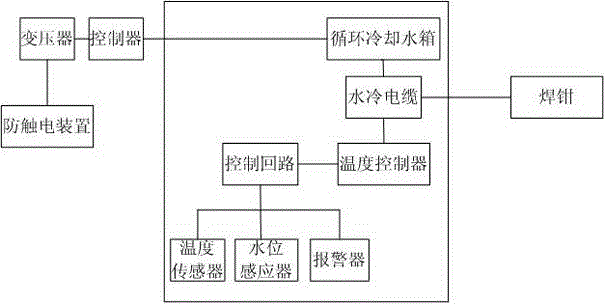
[0019] Such as figure 1 As shown, this embodiment includes a transformer, a controller, a circulating cooling water tank, a water-cooling cable and welding tongs. The transformer is connected to the circulating cooling water tank and the controller respectively. The water-cooling cable passes through the circulating cooling water tank. connected, and also includes a water flow preventer arranged in the circulating cooling water tank, the water flow preventer is connected with the controller, and the top of the transformer is provided with a cooling fan. When the equipment is powered on, turn on the water inlet switch on the circulating cooling water tank. When the cooling circulating water passes through the water flow transmitter, turn on the controller to let the equipment enter the working state; when the cooling water switch is turned off, no cooling water passes through the water flow transmitter. The communication device, the controller cuts off the power supply, and the...

Embodiment 2

[0021] Such as figure 1 As shown, in this embodiment, on the basis of Embodiment 1, the water flow flood control device includes a temperature sensor, a water level sensor, an alarm and a control loop, and the control loop is connected to the temperature sensor, the water level sensor, and the alarm respectively. The control loop is connected with the controller. The control loop is the command center of the water flow preventer. When the water level sensor detects that the water level in the circulating cooling water tank is low, it will transmit a signal to the control loop, and the control loop will control the alarm to sound a buzzer; if the water level in the circulating cooling water tank When the temperature rises sharply due to lack of water, the temperature sensor will transmit the signal to the controller through the control loop, and the controller will directly cut off the power supply to avoid the water-cooled cable from being burned out due to excessive temperatu...

Embodiment 3

[0023] Such as figure 1 As shown, on the basis of Embodiment 1, this embodiment also includes an electric shock prevention device arranged on the input end of the transformer. When a welding machine is empty, the voltage of the DC welding machine is 55-90V, and the voltage of the AC welding machine is 60-80V, both of which exceed the safe voltage value, but because the voltage is not very high, it is often ignored, especially when the welder is exposed to electricity The risk is relatively high. According to the calculation, when the no-load voltage of the welding machine is 70V, the human body is operating in a humid place, and the protective equipment is not properly worn. At this time, the human body resistance RR is about 1600Ω. If the welder's hand touches the jaws, the current IR = V / RR=70 / 1600=0.044A=44MA, under the action of this current, the welder’s hand will convulse, causing ventricular fibrillation. If the rescue is not timely, there will be a risk of death. The ...


PUM


Abstract

The invention discloses an electric welding machine comprising a transformer, a controller, a circulating cooling water tank, a water-cooled cable and an electrode holder. The transformer is connected with both the circulating cooling water tank and the controller. The water-cooled cable penetrates the circulating cooling water tank. The electrode holder is connected with the transformer through the water-cooled cable. The electric welding machine further comprises a flood preventer disposed inside the circulating cooling water tank. The flood preventer is connected with the controller. A cooling fan is disposed on the top of the transformer. During running of the electric welding machine, the transformer also produces heat, and untimely treatment may lead to damage of the transformer; the cooling fan can bring away a great deal of generated heat, and running stability of the transformer is guaranteed.

Description

technical field [0001] The invention relates to the field of electric welding, in particular to an electric welding machine. Background technique [0002] In the production process of automobile and other panel products, welding machines and welding robots have become the key equipment to improve production efficiency and ensure product quality. According to the working characteristics of the equipment, taking corresponding protection measures can ensure the safety and energy saving of the equipment Effect. The welding machine has greatly improved the productivity of the enterprise, and the product competitiveness has also been greatly improved. However, in the process of using, many shortcomings have also been found. The reason is that the service life of the water cable of this equipment is too short, the damage is too fast, and the replacement frequency is too high. This not only causes the equipment to be shut down frequently for maintenance, which affects production, ...

Claims


Application Information

Patent Timeline
Patent Type & Authority Applications(China)
IPC IPC(8): B23K9/00B23K9/10B23K9/32B23K37/00
CPCB23K9/323B23K37/003B23K37/006
Inventor 张丹
Owner 张丹
Why Eureka
Try Eureka