Milling machine waste collection device

A waste collection and milling machine technology, which is applied in the direction of milling machine equipment, milling machine equipment details, metal processing machinery parts, etc., can solve the problem of low efficiency of collecting iron filings, achieve the effect of reducing work intensity, improving efficiency, and ensuring cleanliness

Inactive Publication Date: 2015-03-18
陈均
View PDF0 Cites 7 Cited by
  • Summary
  • Abstract
  • Description
  • Claims
  • Application Information

AI Technical Summary

Problems solved by technology

[0003] The present invention solves the problem of low efficiency of collecting iron filings by setting a milling machi

Method used


Image

  • Milling machine waste collection device

Examples


Example Embodiment

[0020] Example 1

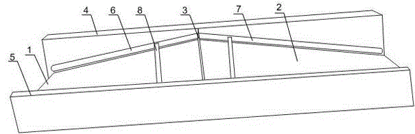
[0021] Such as figure 1 As shown, this embodiment includes a plurality of sequentially connected collection units, and the collection units are arranged at the bottom of the external milling machine. The collection unit includes an inclined left bottom plate 1, an inclined right bottom plate 2, a first baffle 4, a second baffle 5 and a connecting plate 3. The top end of the left bottom plate 1 is connected with the top end of the right bottom plate 2. 3 is set at the junction of the left bottom plate 1 and the right bottom plate 2, the first baffle 4 and the second baffle 5 are respectively set on both sides of the left bottom plate 1 and the right bottom plate 2, and the first baffle 4 and the second baffle 5 pass The connecting plate 3 is connected; the first baffle 4 is provided with a slideway A6 and a slideway B7, and also includes a cleaning mechanism 8 slidably arranged on the slideway A6 and the slideway B7. The traditional recycling mechanism is a fl...

Example Embodiment

[0023] Example 2

[0024] Such as figure 1 As shown, in this embodiment on the basis of embodiment 1, the angle formed between the left bottom plate 1 and the right bottom plate 2 is 120-150°. Within the angle range of 120-150°, the operator can quickly collect iron filings and engine oil by using the inclined plane. When it is higher than the range of 120~150°, the left bottom plate 1 and the right bottom plate 2 are not inclined obviously, the iron filings and oil will slide slowly during collection, and the collection efficiency will be low; when it is lower than the range of 120~150°, the generated iron filings and Engine oil is easy to be scattered directly on the ground, which is not conducive to collection.

Example Embodiment

[0025] Example 3

[0026] Such as figure 1 As shown, this embodiment is based on the first embodiment. The cleaning mechanism 8 includes a cleaning rod and bristles arranged on the cleaning rod. The length of the cleaning rod is equal to the width of the left bottom plate 1 and the right bottom plate 2. The cleaning rod is slidably arranged on the slideway A6 or the slideway B7. When the cleaning rod is pulled, the bristles move downward along the slope, and the bristles push the debris on the left bottom plate 1 or the right bottom plate 2 downward to collect.


PUM

PropertyMeasurementUnit
Angleaaaaaaaaaa

Abstract

The invention discloses a milling machine waste collection device which comprises a plurality of collecting units which are connected in sequence. The collecting units are arranged at the bottom of an external milling machine. A great deal of metal scraps are produced from milling machining of large-sized workpieces, one or more milling machines can be subjected to centralized waste collection through the collecting units arranged at the bottom of the milling machine, efficiency of overall machining procedure of the milling machine is greatly improved, and cleanliness of the operating environment is guaranteed.

Description

technical field [0001] The invention relates to the field of mechanical processing, in particular to a milling machine waste collecting device. Background technique [0002] Compared with the horizontal milling machine, the main difference between the vertical milling machine and the horizontal milling machine is that the spindle is arranged vertically. In addition to the different spindle layout, the workbench can be lifted up and down. The milling cutter used for the vertical milling machine is relatively flexible and has a wide range of applications. , Machine clip cutter head, drill bit for keyway milling, plane milling, boring and other processes. After the processing of the large milling machine is completed, a lot of iron filings or engine oil will be generated on the plane at the bottom of the milling machine. If it is not handled in time, when the accumulation is too large, it is easy to cause the iron filings to hurt the staff's feet or pollute the operating enviro...

Claims


Application Information

Patent Timeline
IPC IPC(8): B23Q11/00B23C9/00
CPCB23Q11/0067B23C9/00
Inventor 陈均
Owner 陈均
Why Eureka
Try Eureka