Multi-nozzle type gas burner

A gas burner and multi-nozzle technology, applied in the direction of burner, combustion method, combustion type, etc., can solve the problems of high maintenance cost, small pulse control control range, short service life, etc., and achieve simplification of overall structure and pipeline design , Operational reliability performance improvement, energy saving and environmental protection benefits

Active Publication Date: 2015-03-18
SHEN KAN QINHUANGDAO GENERAL ENG DESIGN & RES INST CORP MCC
View PDF5 Cites 3 Cited by
  • Summary
  • Abstract
  • Description
  • Claims
  • Application Information

AI Technical Summary

Problems solved by technology

[0003] With the development of computer and automatic control technology, the pulse combustion control method is used instead of the pipeline flow regulation method to adjust the heating capacity of the burner, and the flow regulation valve is set as an automatic valve with only two states of cut-off and open. However, based on The adjustment of the heating capacity in the above way requires the modification of pipelines or valves. For example, automatic quick cut-off valves are installed on each air and gas pipeline connected to the burner, or complex pipelines need to be installed to To ensure the continuous burning of the flame, the structure of the modified system is complex and the maintenance cost is high
In addition, because the ratio between small and large fires is still limited by the air-fuel ratio, for burners with low power, the adjustment ratio is often less than 2, resulting in a very small control range of pulse control and is difficult to control. For burners with higher power, the production cost of large-diameter shut-off valves is expensive and the service life is short

Method used


Image

  • Multi-nozzle type gas burner
  • Multi-nozzle type gas burner
  • Multi-nozzle type gas burner

Examples


Embodiment Construction

[0039] The following will further describe the multi-jet gas burner according to the present invention according to specific embodiments and accompanying drawings, but this description does not constitute an improper limitation of the present invention.

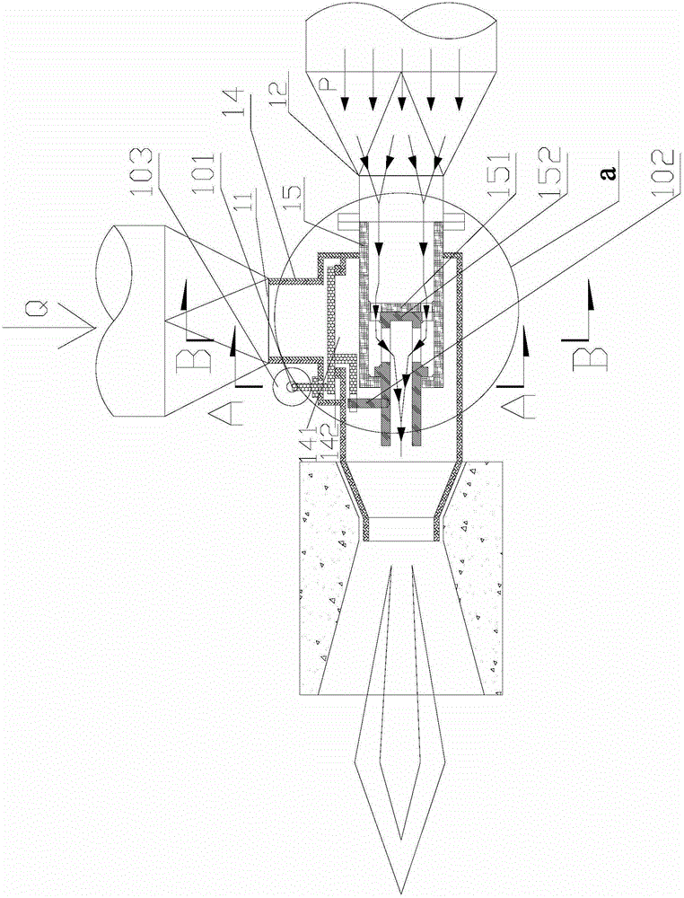
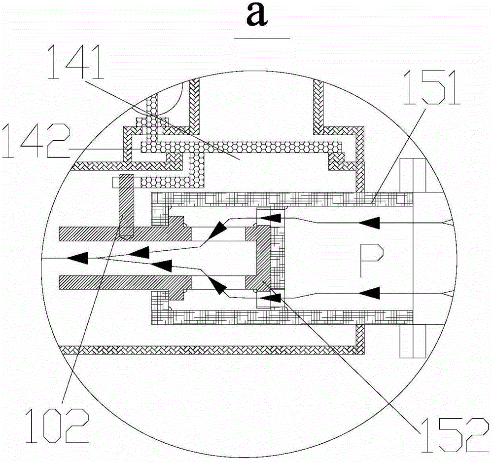
[0040] figure 1 It shows the structure of the multi-jet gas burner provided by the present invention in the state where the main jet is in the longitudinal section in this embodiment, figure 2 The structure of the main jet air valve and the main jet gas valve in the multi-nozzle gas burner is specifically shown.

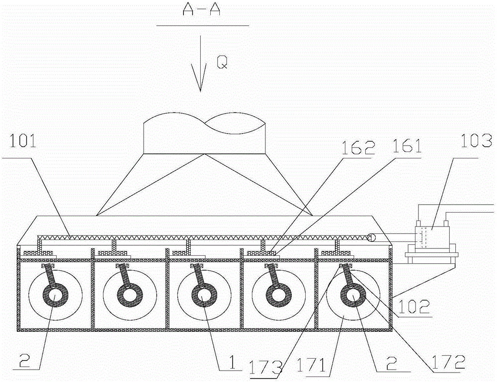
[0041] In this embodiment, the multi-jet gas burner includes an air box, a gas box, a main nozzle and four auxiliary nozzles, the auxiliary nozzles are arranged around the main nozzle, and air is stored in the air box. 30% CO gas. Such as figure 1 and figure 2 As shown, an air inlet 11 is provided on the air box, and air enters into the air box through the air inlet 11, and a gas inlet 12 is provided on the ga...


PUM


Abstract

The invention discloses a multi-nozzle type gas burner. The multi-nozzle type gas burner comprises an air box body, a gas box body, at least one main nozzle and at least two auxiliary nozzles, the main nozzle is communicated with the air box body through a main nozzle air valve and communicated with the gas box body through a main nozzle gas valve; the main nozzle air valve comprises a first half-open state and a second fully-open state; the main nozzle gas valve comprises a first half-open state and a second fully-open state; every auxiliary nozzle is communicated with the air box body through an auxiliary nozzle air valve and communicated with the gas box body through an auxiliary nozzle gas valve; every auxiliary nozzle air valve comprises a first fully-closed state and a second fully-open state; every auxiliary nozzle gas valve comprises a first fully-closed state and a second fully-open state; the number of the auxiliary nozzles is larger than that of the main nozzle; the auxiliary nozzles are arranged on the periphery of the main nozzle; the main nozzle air valve, the auxiliary nozzle air valves, the main nozzle gas valve and the auxiliary nozzle gas valves are synchronously driven by a driving device to be switched between the corresponding first states and the corresponding second states.

Description

technical field [0001] The invention relates to a gas burner, in particular to a gas burner used in a pulse control combustion system. Background technique [0002] At present, flow regulating valves are usually installed on the gas and air pipelines or the opening degree of the valve plate inside the valve is adjusted to increase or decrease the flow of the pipelines, thereby realizing the adjustment of the heating capacity of the gas burner. However, since the burners are designed according to the optimum flow rate, they cannot be adjusted arbitrarily. The more the changed flow deviates from the optimal flow, the worse the combustion situation will be, and finally a continuous and reliable combustion flame cannot be formed. Therefore, for the burner nozzle designed according to the optimal flow, the flow adjustment range is extremely limited. limited. Generally, the adjustable range is called the adjustment ratio. The adjustment ratio of most burners is kept at 3 times, ...

Claims


Application Information

Patent Timeline
Patent Type & Authority Applications(China)
IPC IPC(8): F23D14/58F23D14/60
CPCF23D14/58F23D14/60
Inventor 吕东方
Owner SHEN KAN QINHUANGDAO GENERAL ENG DESIGN & RES INST CORP MCC
Why Eureka
Try Eureka