Circuit of shifting register, and gate drive circuit, display device comprising same

A shift register and circuit technology, applied in the fields of shift register circuits, gate drive circuits, and display devices, can solve the problems of high energy consumption of gate drivers and large substrate area occupied by the circuit, and achieve the function of bidirectional scan switching. , optimize circuit design and meet market demand

Inactive Publication Date: 2015-03-18
AU OPTRONICS CORP
View PDF0 Cites 11 Cited by
  • Summary
  • Abstract
  • Description
  • Claims
  • Application Information

AI Technical Summary

Problems solved by technology

[0005] More importantly, since the gate driver has a great influence on the display picture quality of the liquid crystal display, although the shift register circuit in the prior art can realize forward and reverse signal transmission, the circuit scale is too large and there are too many control signals. It will directly lead to high energy consumption of the gate driver and a large substrate area occupied by the circuit. Therefore, how to design a shift register circuit with a simple circuit and low energy consumption to improve the performance of the gate driver and reduce its occupation Substrate area is one of the directions that the industry is committed to

Method used


Image

  • Circuit of shifting register, and gate drive circuit, display device comprising same
  • Circuit of shifting register, and gate drive circuit, display device comprising same
  • Circuit of shifting register, and gate drive circuit, display device comprising same

Examples


Embodiment Construction

[0050] In order to have a further understanding of the purpose, structure, features, and functions of the present invention, the following detailed descriptions are provided in conjunction with the embodiments.

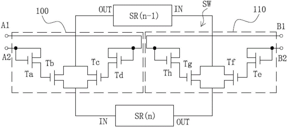
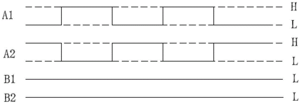
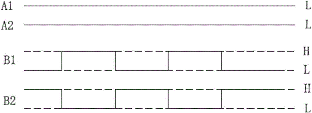
[0051] Please refer to image 3 , is a partial circuit structure diagram of the display device in an embodiment of the present invention. In this embodiment, the display device 1 includes: a substrate 10; a pixel array 12, which is patterned and formed on the substrate 10, and the pixel array 12 includes a plurality of pixel units (not shown in the figure); a gate driving circuit 11, which It includes a shift register circuit 14 formed by cascade coupling of a plurality of shift registers SR(1)-SR(n+m), a trigger signal source, a start trigger signal source and a first voltage source, wherein the trigger The signal source is used to provide the first trigger signal A and the second trigger signal B to the shift register circuit 14, and the start trigger signal source...


PUM


Abstract

The invention provides a circuit of a shifting register, and a gate drive circuit, a display device comprising the same, wherein the circuit of the shifting register comprises a plurality of shifting registers, a first switch circuit, and a second switch circuit, wherein the shifting registers are electrically coupled in a cascade mode and are used for outputting a plurality of scanning signals; the first switch circuit is used for transmitting the scanning signal outputted by each shifting register along the forward direction through the control of a first triggering signal; the second switch circuit is used for transmitting the scanning signal outputted by each shifting register along the reverse direction through the control of a second triggering signal; the first triggering signal and the second triggering signal are reverse on phase. By adopting the circuit of the shifting register, and the gate drive circuit, the display device comprising the same, the circuit scale of the circuit of the shifting register is simplified, the use of a transistor is reduced, the energy consumption of the circuit of the shifting register is reduced, and the dual-direction scanning switching function is realized for meeting a relatively large quantity of market demands.

Description

technical field [0001] The invention relates to the field of display technology, in particular to a shift register circuit with simple circuit structure, low energy consumption and capable of realizing bidirectional scanning switching function, a gate drive circuit and a display device including the shift register circuit. Background technique [0002] In today's era of rapid technological development, liquid crystal displays have been widely used in electronic display products, such as televisions, computer screens, notebook computers, mobile phones or personal digital assistants. The liquid crystal display includes a source driver (Source Driver), a gate driver (Gate Driver) and a liquid crystal display panel, wherein the liquid crystal display panel has a pixel array, and the gate driver is used to sequentially turn on corresponding pixel columns in the pixel array to The pixel data output by the data driver is input to the pixels, and then the image to be displayed is di...

Claims


Application Information

Patent Timeline
Patent Type & Authority Applications(China)
IPC IPC(8): G11C19/28G09G3/36
Inventor 王柏凯黄俊豪
Owner AU OPTRONICS CORP
Why Eureka
Try Eureka