Flywheel Power Generation Structure

A flywheel and electric energy technology, applied in the field of damping mechanism, can solve the problems of energy waste, unfavorable production and high cost of materials, etc.

Inactive Publication Date: 2015-03-18
DIRECTION TECH
View PDF4 Cites 3 Cited by
  • Summary
  • Abstract
  • Description
  • Claims
  • Application Information

AI Technical Summary

Problems solved by technology

[0006] In addition, when athletes use traditional fitness equipment for exercise, traditional fitness equipment often cannot effectively recover the energy generated by the athlete during exercise, resulting in energy waste
[0007] However, the speed of the flywheel depends on the speed generated by the pedaling force applied by the athlete, which further affects the power generation efficiency. When the speed generated by the pedaling force applied by the athlete is slow, the power generation efficiency of the generator set is also poor. Therefore, how to effectively improve the power generation efficiency of the generator set has become an important issue.
[0008] The disadvantages of this existing structure include: large volume, low power generation at low speed, relatively expensive material costs that are not conducive to manufacturing, high temperature during operation, difficult assembly, and high labor costs

Method used


Image

  • Flywheel Power Generation Structure
  • Flywheel Power Generation Structure
  • Flywheel Power Generation Structure

Examples


Embodiment Construction

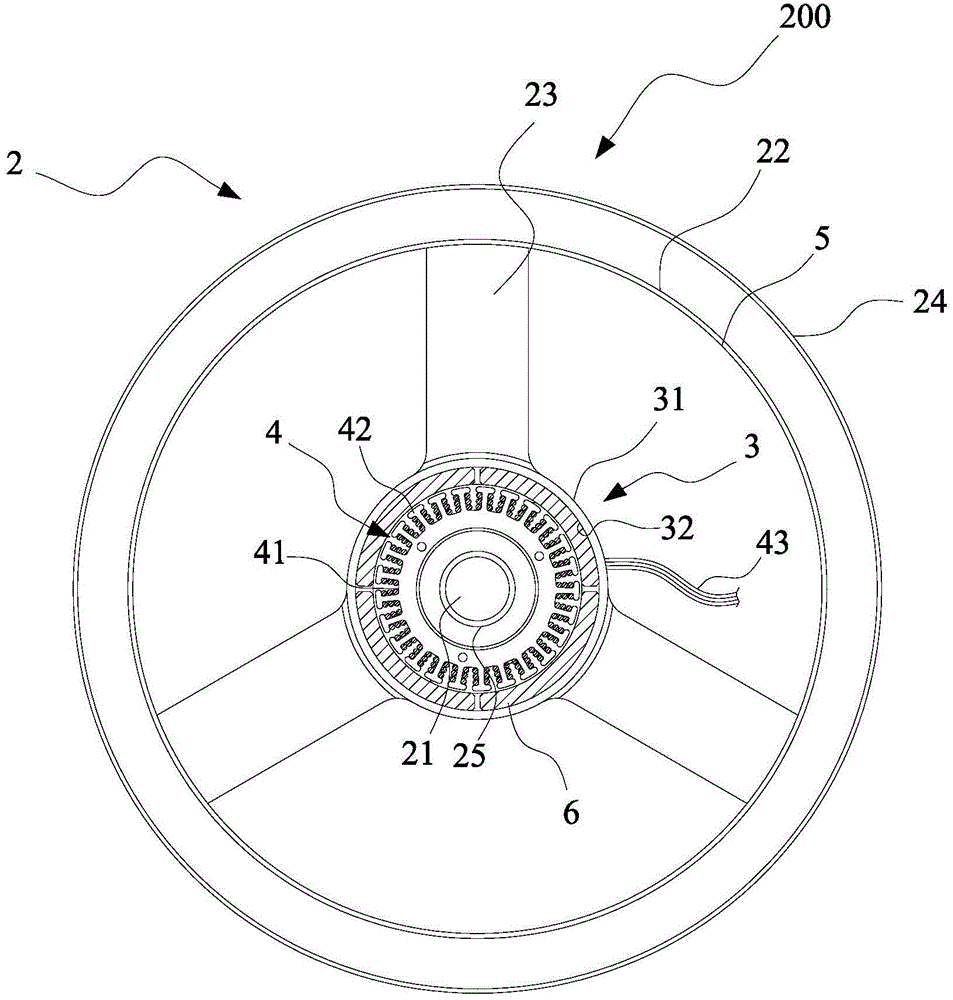
[0068] see figure 2 , showing a schematic diagram of the flywheel body. As shown in the figure, a flywheel generating structure 200 includes a flywheel body 2 , an inner ring 3 and a coil assembly 4 .

[0069] The selected position of the flywheel body 2 has a shaft portion 21, a flywheel inner side 22, two side surfaces 23 and a flywheel outer side 24. The flywheel inner side 22 is combined with a metal ring 5 to make the inertial rhythm of the flywheel body 2 rotation more stable. The material used for the metal ring 5 is a non-magnetic material, such as aluminum and copper as the medium material.

[0070] The shaft portion 21 of the flywheel body 2 is rotatably combined with a rotating shaft 25 , so that the flywheel body 2 is rotated by an external driving force with the rotating shaft 25 as the center of rotation.

[0071] The inner ring 3 integrally extends a length from one of the side surfaces 23 of the flywheel body 2 , the inner ring 3 has an outer ring side 31 an...


PUM


Abstract

The present invention provides a flywheel power generation structure. The flywheel power generation structure comprises a flywheel body, an inner ring, a plurality of magnetic units, a coil assembly. The flywheel body can be combined with a rotating shaft rotatably, and possesses a shaft part, a flywheel inner side, two side surfaces and a flywheel outer side. One of the two side surfaces of the flywheel body extends out of the inner ring, and the inner ring possesses an outer ring side surface and an inner ring surface, wherein the plurality of magnetic units are arranged on the inner ring surface of the inner ring annularly, the coil assembly is wound on a plurality of magnetic poles of a coil carrier, and a pair of electric power output lines are extended out from the coil assembly. The coil carrier is combined in the axis of the rotating shaft as a stator, when the flywheel body rotates, the inner ring and the magnetic units rotate along with the flywheel body, and the coil assembly senses the electric energy, and the electric power output lines output the electric energy to a brake device. The flywheel power generation structure also comprises an electromagnetic brake device. The flywheel power generation structure has the advantages of generating power efficiently, increasing inertia and saving materials.

Description

technical field [0001] The invention relates to a damping mechanism, especially a flywheel power generation structure applied to fitness equipment. Background technique [0002] In traditional fitness equipment, such as exercise bikes, athletes mainly step on the pedals to drive the flywheel on the exercise bike to rotate. The way of magnetic resistance provides the adjustment of different resistance levels of the exercise bike, so that athletes can achieve the effect of exercise and fitness by fighting against different resistance or resistance. [0003] The structure of the planetary gear is arranged on the inner ring surface of the flywheel of the existing exercise bike, and the purpose of generating electricity is achieved through the structure of a plurality of gears meshing. The disadvantages of this existing structure include: various gears and gear discs are required to form a complex gear structure, high material costs, high noise during gear operation, difficult a...

Claims


Application Information

Patent Timeline
Patent Type & Authority Applications(China)
IPC IPC(8): H02K7/02H02K7/10
CPCY02E60/16H02K7/025H02K7/10
Inventor 陈穗荣
Owner DIRECTION TECH
Why Eureka
Try Eureka