Multi-station hot forming device and hot forming method for high-strength parts

A multi-station, hot forming technology, applied in the field of hot stamping of high-strength parts, can solve the problems of long production cycle, high requirements for equipment coordination, and many equipments, so as to achieve strong practicability and save laser drilling and cutting. The effect of side processes

Active Publication Date: 2015-03-25
东莞市豪斯特热冲压技术有限公司 +1
View PDF7 Cites 21 Cited by
  • Summary
  • Abstract
  • Description
  • Claims
  • Application Information

AI Technical Summary

Problems solved by technology

The whole process includes blanking, heating, conveying, forming quenching, punching and edge trimming. The whole process involves many processes, which requires a high degree of equipment coordination and long production cycle, which affects production efficiency. The required mechanical equipment Multiple and complex, large investment, large space occupation
The roller hearth heating furnace or multi-layer box heating furnace takes a long time to complete the austenitization of the high-strength steel billet. During the transportation of the hot billet, it is easy to be oxidized, the temperature drops greatly, and the heat loss is large. The transportation process requires There are a lot of equipment, large investment, and high requirements for the coordination of equipment, and the surface quality of hot blanks affects the quenching process of hot forming and the quality of final parts; High strength and high hardness, the traditional cold stamping die cannot complete the punching and edge trimming process, so laser equipment is needed to complete the punching and edge trimming process of thermoformed parts

Method used


Image

  • Multi-station hot forming device and hot forming method for high-strength parts
  • Multi-station hot forming device and hot forming method for high-strength parts
  • Multi-station hot forming device and hot forming method for high-strength parts

Examples


Embodiment Construction

[0023] In order to facilitate the understanding of those skilled in the art, the present invention will be further described below in conjunction with the embodiments and accompanying drawings, and the contents mentioned in the embodiments are not intended to limit the present invention.

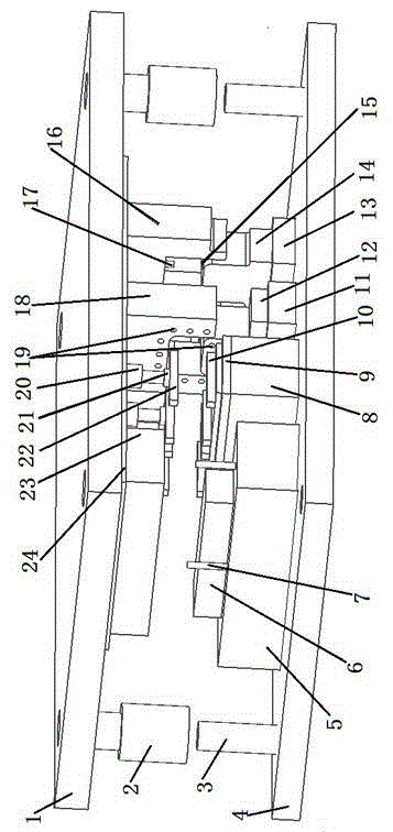
[0024] Such as figure 1 As shown, a multi-station thermoforming device for high-strength parts includes an upper mold frame 1, a lower mold frame 4, a forming die 18 arranged on the upper mold frame 1, and a forming punch 12 arranged on the lower mold frame 4. The upper mold frame 1 is equipped with a movable heating component 22 and a lifting drive device 20 for driving the movable heating component 22 to rise and fall, and the lower mold frame 4 is equipped with a fixed heating component 10. The fixed heating component 10 and the movable heating component 22 on the upper mold frame 1 are arranged corresponding to each other.

[0025] Preferably, the upper die frame 1 is equipped with a fo...


PUM


Abstract

The invention relates to the technical field of hot stamping of high-strength parts, in particular to a multi-station hot forming device and a hot forming method for high-strength parts. The hot forming device comprises an upper die carrier, a lower die carrier, a forming female die and a forming male die. The upper die carrier is provided with a movable heating component, and the lower die carrier is provided with a fixed heating component. The hot forming method comprises the steps that firstly, machined blanks are conveyed to the fixed heating component for local heating, so that hot blanks are obtained; the forming male die and the forming female die mutually draw close to perform die assembly forming, so that the hot forming parts are obtained. Quick local conduction heating and forming quenching of the blanks are synchronously completed on a press machine, so that the heating time of the blanks is shortened, and heating efficiency is improved. Meanwhile, conveying equipment for heating furnaces and hot blanks and the conveying process in a traditional hot forming technology are omitted, heat loss of the hot blanks in the conveying process and oxidation of the surfaces of the hot blanks are avoided, and therefore the surface quality of the blanks and the quality of the final hot forming parts are guaranteed.

Description

technical field [0001] The invention relates to the technical field of hot stamping of high-strength parts, in particular to a multi-station thermoforming device and a thermoforming method for high-strength parts. Background technique [0002] Hot forming technology is a new technology for forming high-strength steel stamping parts by combining stamping and heat treatment. The blanks become ultra-high-strength parts, which are widely used in the production of automobile security parts and car body structural parts. [0003] Traditional hot forming process: First, the prefabricated blank is obtained by stamping die or laser cutting, and then the complete austenitization process of the high-strength steel prefabricated blank is completed in a roller hearth heating furnace or a multi-layer box heating furnace, and then through industrial robots and machines The hot blank is delivered to the mold by hand, and then the forming quenching and pressure holding process of the hot bl...

Claims


Application Information

Patent Timeline
Patent Type & Authority Applications(China)
IPC IPC(8): B21D37/10B21D37/16B21D35/00
CPCB21D22/022B21D35/002B21D37/10B21D37/16
Inventor 张宜生梁卫抗姚小春
Owner 东莞市豪斯特热冲压技术有限公司
Why Eureka
Try Eureka