Laser real-time deviation correction device and deviation correction method

A laser, high-speed technology, used in laser welding equipment, welding equipment, metal processing equipment, etc., can solve the problems of reduced production efficiency, waste, and non-compliance of amorphous silicon thin-film solar cell chips, to improve processing efficiency, time consumption, etc. short effect

Active Publication Date: 2017-01-25
SUZHOU DELPHI LASER +1
View PDF6 Cites 0 Cited by
  • Summary
  • Abstract
  • Description
  • Claims
  • Application Information

AI Technical Summary

Problems solved by technology

Accompanied by each marking, there is a possibility that the scoring line groove deviates from the previous scoring groove and crosses. If the deviation of the upcoming scoring groove relative to the previous scoring groove is not corrected in time before marking, it will There will be adhesion and short circuit on both sides of the scribed groove or the width of the three scribed grooves plus the distance between them exceeds 0.5mm, resulting in defective or waste products, which not only reduce production efficiency but also waste. Amorphous silicon thin-film solar cell chips often therefore do not meet the requirements

Method used


Image

  • Laser real-time deviation correction device and deviation correction method

Examples


Embodiment Construction

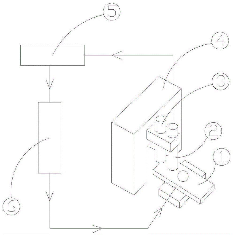
[0022] Such as figure 1 As shown in the real-time laser deviation correction device, there is a marble beam 4 above the moving working platform 1, and the alignment high-speed lens 2 and the laser processing head 3 are installed on the marble beam 4. The alignment high-speed lens 2 is produced by OLYMPUS Olympus in Japan LCPLN50XIR lens, motion control unit 6 is ACS main controller SpiiplusNtm-16000000NNN-S, motion working platform 1 is an X-Y axis motion platform, including the Y axis unit in the cutting direction and the X axis unit in the fixed distance moving direction combined with it; alignment The high-speed lens 2 and the laser processing head 3 are facing the moving working platform 1, and the alignment high-speed lens 2 and the laser processing head 3 are connected to the computer 5 through communication. The unit 6 is connected in communication, and the motion control unit 6 is connected with the motion working platform 1 under control. Laser real-time deviation co...


PUM


Abstract

The invention relates to a laser real-time deviation correction device and a deviation correction method of the laser real-time deviation correction device. A cross beam is arranged above a moving working platform. High-speed alignment lenses and laser processing heads are mounted on the cross beam. The high-speed alignment lenses and the laser processing heads are aligned with the moving working platform. The high-speed alignment lenses and the laser processing heads conduct communication connection with a computer. Evision pattern recognition calculation software is installed in the computer. The computer conducts communication connection with a movement control unit. The movement control unit is in control connection with the moving working platform. Laser real-time deviation correction is conducted in the moving process of the platform, the high-speed alignment lenses mounted on the marble cross beam are used for quickly shooting and capturing images and transmitting the images to the computer, the computer processes the images, calculates positional deviation and transmits a deviation instruction to the movement control unit, the movement control unit sends an instruction to compensate for movement of the moving working platform, and then high-precision and accurate laser processing is realized. Real-time deviation correction is completed in the processing and moving process, the consumed time is extremely short, and the processing efficiency is greatly improved.

Description

technical field [0001] The invention relates to a real-time laser deviation correction device and a deviation correction method thereof. Background technique [0002] With the continuous development of laser technology, laser processing technology (such as laser marking, laser welding or laser engraving, etc.) is more and more widely used in various precision processing. At present, the relatively mature amorphous silicon thin-film solar cell chips use laser to scribe their electrodes. There are three laser scribed grooves. The technical requirements for the scribed grooves are: the scribed grooves are smooth and clear, and there are no Adhesive short circuit, the three scribed grooves are parallel to each other, and the width of the three scribed grooves plus the distance between them shall not exceed 0.5mm. Accompanied by each marking, there is a possibility that the scoring line groove deviates from the previous scoring groove and crosses. If the deviation of the upcomin...

Claims


Application Information

Patent Timeline
Patent Type & Authority Patents(China)
IPC IPC(8): B23K26/70B23K26/03B23K26/00
CPCB23K26/00B23K26/032
Inventor 赵裕兴李军叶浩
Owner SUZHOU DELPHI LASER
Why Eureka
Try Eureka