Grabbing pneumatic connecting rod arm with double-paw structure

A connecting rod arm and gripper technology, which is applied in the field of pneumatic connecting rod arm for grasping, can solve the problems of natural cooling time influence, prolonging the processing cycle, affecting production efficiency, etc. The effect of improving production tact and efficiency

Inactive Publication Date: 2015-03-25
HEFEI UNIV OF TECH
View PDF6 Cites 22 Cited by
  • Summary
  • Abstract
  • Description
  • Claims
  • Application Information

AI Technical Summary

Problems solved by technology

The parts that need to be hot-formed, such as the car stabilizer bar in the past, are in a high-temperature environment with a low degree of automation. Many processes from the furnace to the processing to the quenching are completed by manual clamping. The long natural cooling time seriously affects the quality of the product, and the long-term high-temperature environment has a direct or indirect impact on the adverse factors of the human body
Although the domestic auto industry has improved in the automatic processing of the thermoforming process of the stabilizer bar, most of the automatic production of thermoforming processing uses robotic automation equipment with one-handed grippers, and only one part can be realized at a time using a single-handed gripper Pick and place, such as grabbing a part at a time, placing it for processing, and the process of processing a part means waiting for a single-handed claw. After processing, take it down and place it, and grab the next part again. To prolong the tact of processing, affect the efficiency of production, the result is to increase the production cost of the enterprise

Method used


Image

  • Grabbing pneumatic connecting rod arm with double-paw structure
  • Grabbing pneumatic connecting rod arm with double-paw structure
  • Grabbing pneumatic connecting rod arm with double-paw structure

Examples


Embodiment

[0029] The use workflow of the present invention is as follows:

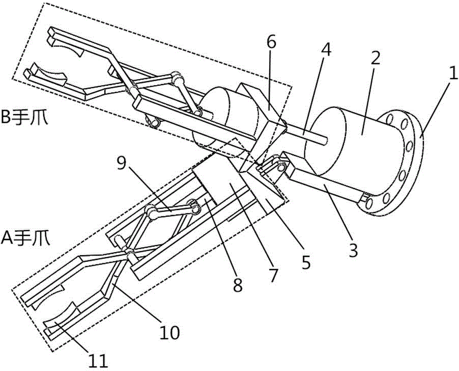
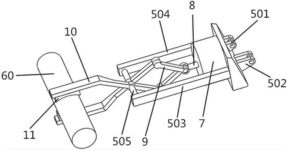
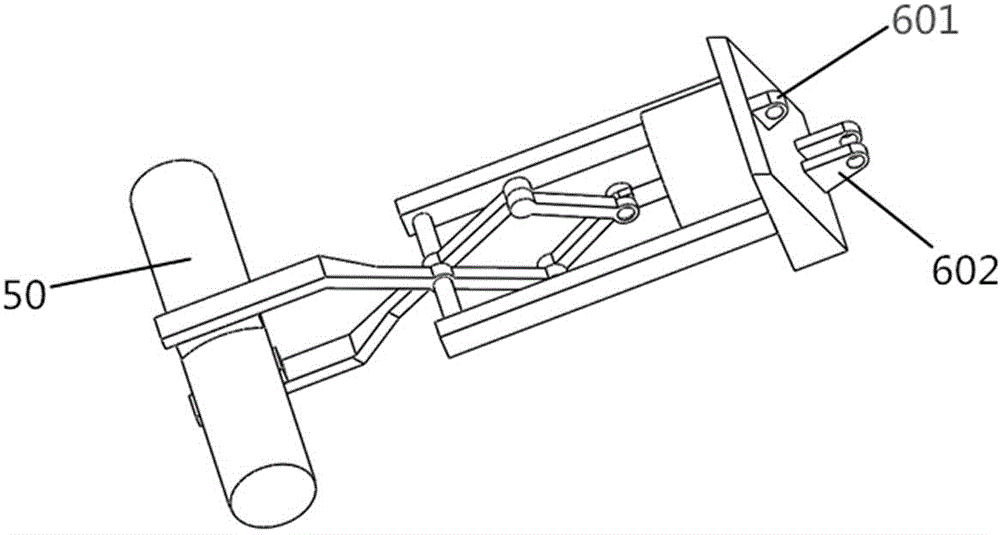
[0030] see figure 1 and 2 . When the claw is clamping the part, the cylinder extension rod extends to push the scissor linkage mechanism to move, so that the opening of the left and right fingers gradually increases, and the opened left and right fingers move to the part, and the cylinder extension rod shrinks , the opening of the left and right hands gradually decreases, and the workpiece is clamped.

[0031] see figure 1 and 4 . During parts processing, the claw of A grasps the part and waits. After the processing is completed, the extension rod 4 of the claw indexing cylinder is stretched out until the claw of B is level. B claws grab the processed parts.

[0032] see figure 1 and 5 . Claw rotates cylinder extension rod 4 and retracts until A claw is horizontal, and now the axis of the connecting hole connected at three places of the base is still an equilateral triangle.

[0033] During the movem...


PUM


Abstract

The invention relates to a grabbing pneumatic connecting rod arm with a double-paw structure. The grabbing pneumatic connecting rod arm comprises a paw A, a paw B, a shift cylinder seat, a shift cylinder, a mounting plate and the like. The paws A and B have the same structure, and each paw consists of a scissor type connecting rod mechanism and a cylinder bracket. The tail of the shift cylinder and the connecting hole end of the mounting plate are fixedly connected to the same plane end of the cylinder seat, the mounting plate is arranged below the shift cylinder, a single lug hole seat of the mounting plate is hinged to a second connecting seat lug of the paw A through a pin shaft, a first connecting seat lug of the paw A is hinged to a second connecting seat lug of the paw B, and the second connecting seat lug of the paw B is hinged to an extension rod of the shift cylinder through a pin shaft. The telescopic motion of the extension rod of the paw shift cylinder drives the two paws to shift, so that workpieces can be alternately charged or discharged. The grabbing pneumatic connecting rod arm is widely applicable to an automatic part processing production line. The mechanical paws are simple in structure, and a cylinder serves as a driving device, so that the cost is reduced on the premise that the operation can be realized. By using the grabbing pneumatic connecting rod arm, the production time can be shortened, and the production efficiency is improved.

Description

technical field [0001] The invention relates to a pneumatic link arm, in particular to a grabbing pneumatic link arm with a double claw structure. Background technique [0002] At present, the installation and production of many parts in the domestic machinery and automobile industry are completed on automatic assembly lines. However, the demand for automation has put forward many requirements for automation equipment. Parts that need to be thermoformed, such as the automotive stabilizer bar in the past, are in a high-temperature environment with a low degree of automation. Many processes from the furnace to the processing to the quenching are completed by manual clamping, which is not only inefficient but also due to the The long natural cooling time seriously affects the quality of the product, and the long-term high-temperature environment has a direct or indirect impact on the adverse factors of the human body. Although the domestic automobile industry has improved in t...

Claims


Application Information

Patent Timeline
Patent Type & Authority Applications(China)
IPC IPC(8): B25J9/00B25J15/08B25J18/00B25J13/00
Inventor 黄康洪健赵福民何春生董宇
Owner HEFEI UNIV OF TECH
Why Eureka
Try Eureka