a paint pump

A paint pump and pump body technology, which is applied in the field of fluid pumps, can solve the problems of insufficient suction, low output efficiency, and low output particle size requirements of the paint pump, and achieve the effects of improving service life, reliable performance, and reducing output phenomena

Active Publication Date: 2016-06-08
NINGBO LIS IND
View PDF3 Cites 0 Cited by
  • Summary
  • Abstract
  • Description
  • Claims
  • Application Information

AI Technical Summary

Problems solved by technology

[0007] Specifically, the technical problem to be solved by the present invention is: to provide a paint pump to solve the technical problems of insufficient suction volume, low output granularity requirements, and low output efficiency of the current paint pump

Method used


Image

  • a paint pump
  • a paint pump
  • a paint pump

Examples


Embodiment Construction

[0027] The present invention will be further described below in conjunction with the accompanying drawings and embodiments. However, the uses and purposes of these exemplary embodiments are only used to illustrate the present invention, and do not constitute any form of limitation to the actual protection scope of the present invention, nor limit the protection scope of the present invention thereto.

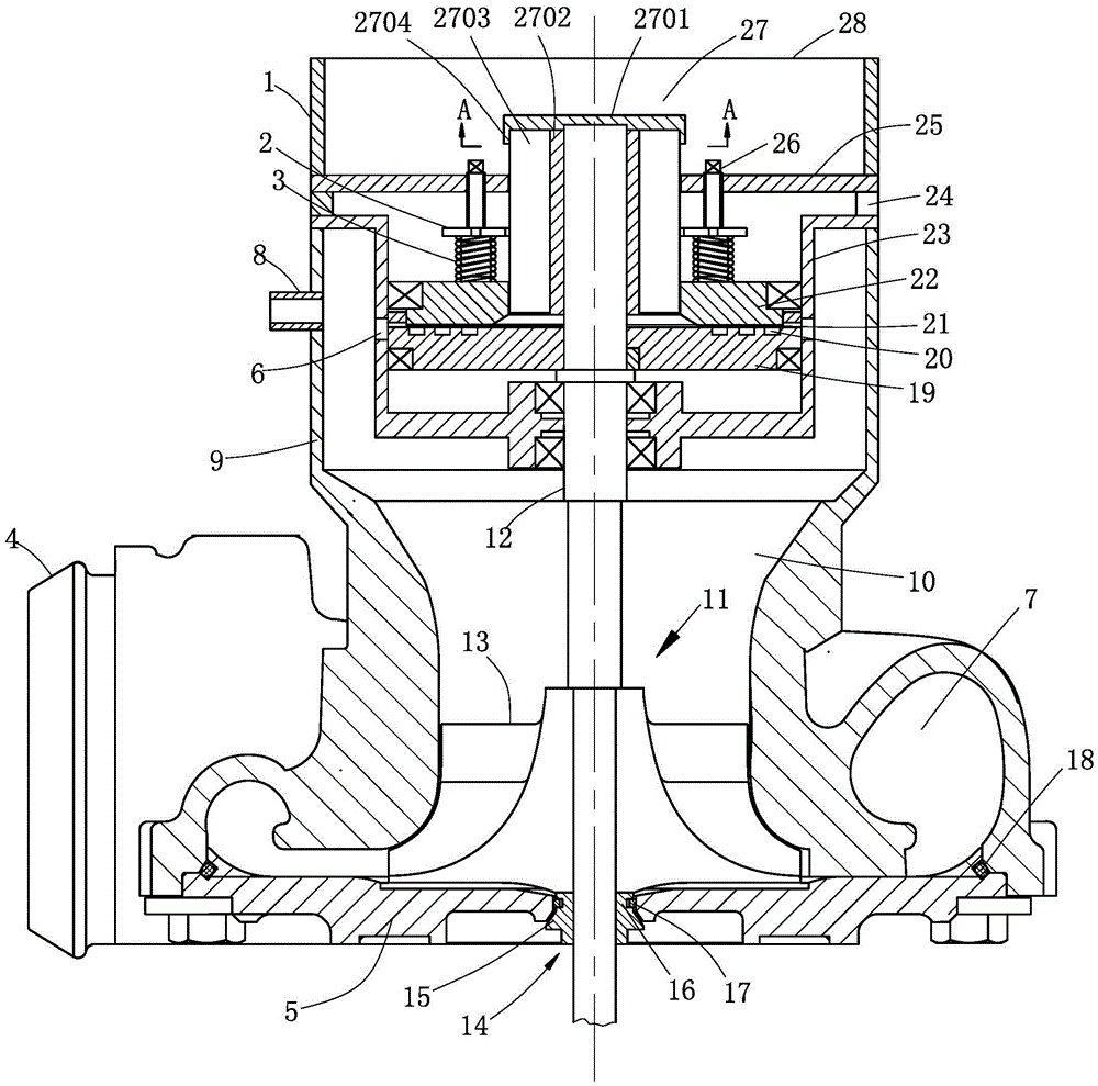
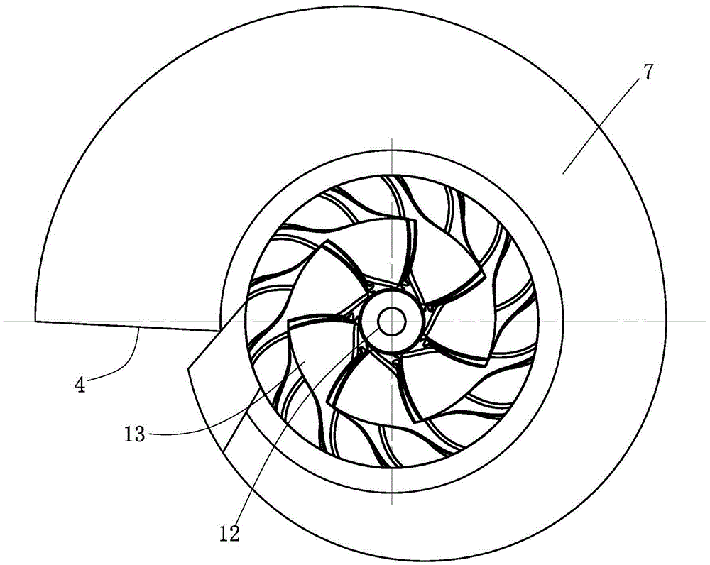
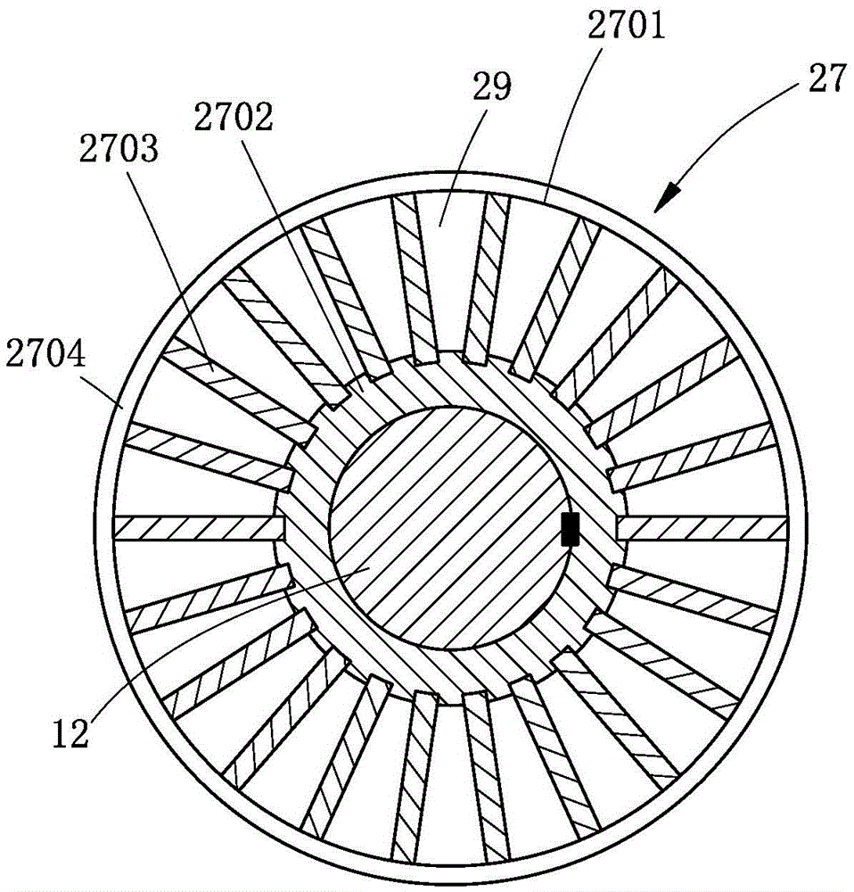
[0028] like figure 1 , figure 2 and image 3Commonly shown, the present invention provides a paint pump, including a pump body, the pump body is a straight cylindrical structure, one end of the pump body is provided with a feed port 28, and the other end is provided with a vortex-shaped vortex channel 7, the pump body is close to The feed inlet 28 is provided with a partition wall 25, and the pump body between the partition wall 25 and the second impeller 11 is provided with a mounting cylinder 23. A closed installation cavity is formed between the mounting cylinder 23 and th...


PUM


Abstract

The invention discloses a coating pump, and belongs to the technical field of fluid pumps. The coating pump comprises a pump body, a feeding port is formed in one end of the pump body, and a vortex-shaped vortex channel is formed in the other end of the pump body. A partition wall is arranged at the position, close to the feeding port, inside the pump body, and an installing tube is arranged at the position, between the partition wall and a plunger piston, inside the pump body. A transmission shaft is installed on the installing tube in a rotating mode and penetrates through an installing cavity, and a rotating disc is fixedly installed at the position, inside the installing cavity, of the transmission shaft. A floating disc is arranged inside the installing cavity, a first impeller is fixedly installed on the transmission shaft, a circulation gap is formed between the floating disc and the rotating disc, and multiple through holes corresponding to the circulation gap are formed in the installing tube. The area of the section of the vortex channel is gradually increased outwards from the center of a vortex, a second impeller is fixedly installed on the transmission shaft and used for guiding fluid into the vortex channel, and a discharging port is formed in the tail end of the vortex channel. The technical problems that an existing coating pump is insufficient in suction volume and low in output efficiency are solved, and the coating pump is widely applied to continuously conveying the fluid.

Description

technical field [0001] The invention relates to a pump, more particularly to a paint pump, and belongs to the technical field of fluid pumps. Background technique [0002] The paint pump is a fluid material conveying device, especially suitable for conveying materials that cannot be damaged, such as oranges, cosmetics containing active agents, blood preparations, biopharmaceuticals, preparations, sucrose containing additives, maltose, etc. [0003] In terms of types, paint pumps are mainly divided into plunger pumps and rotor pumps. Among them, rotor pumps are widely used because they are not easy to clog during delivery. [0004] However, in the field of painting and spraying, there are strict requirements on the particle size of the output fluid materials, and the output of excessively large particle materials is not allowed to affect the spraying effect. In order to solve this problem, the existing treatment measures are to add filter equipment to the pipeline for convey...

Claims


Application Information

Patent Timeline
Patent Type & Authority Patents(China)
IPC IPC(8): F04D7/04
CPCF04D7/04F04D29/007F04D29/083F04D29/22F04D29/445F04D29/708
Inventor 任贤德
Owner NINGBO LIS IND
Why Eureka
Try Eureka