

Railway locomotive vehicle braking clamp unit
A technology for vehicle brake calipers and rail locomotives, which is used in brake actuators, mechanical equipment, gear transmission mechanisms, etc. The effect of high degree of chemical transformation and volume reduction
- Summary
- Abstract
- Description
- Claims
- Application Information
AI Technical Summary
Problems solved by technology
Method used
Image

Examples
Embodiment 1
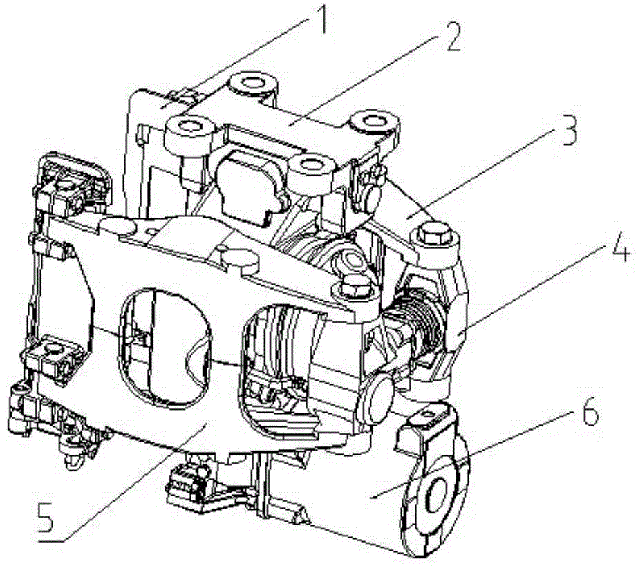
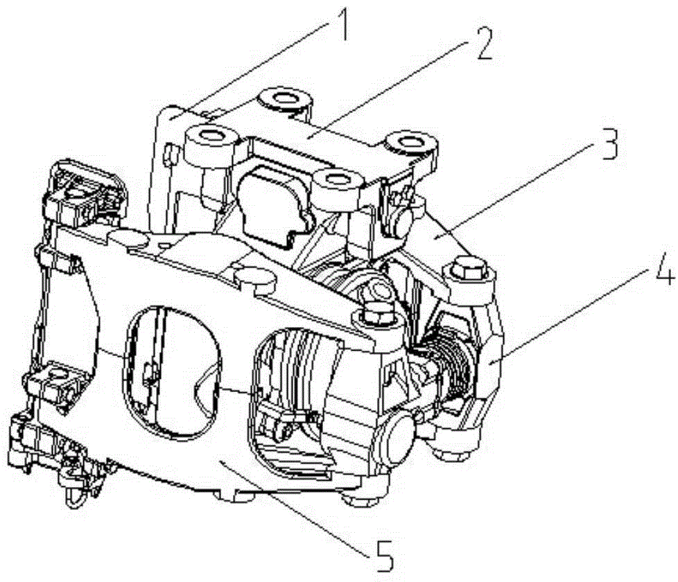
[0036] The rail vehicle brake caliper unit of this embodiment adopts the installation form of a connecting frame. The connecting frame 2 is provided with a threaded mounting hole. The connecting frame 2 is located above the box body 12, and the box body 12 and the connecting frame 2 are connected by pins.
[0037] The rail vehicle brake caliper unit includes a box body 12, a brake cylinder 14, a brake force amplification mechanism, a brake caliper arm, a buffer device and a brake pad clearance adjuster 4, and the front end of the brake caliper arm is connected to a brake pad holder 1 ;
[0038] The brake cylinder 14 is fixedly connected with the casing 12. The brake cylinder 14 includes a diaphragm and a piston rod 16 fixedly connected with the diaphragm. The return tower spring 10 is fixed between the cylinder head of the brake cylinder 14 and the diaphragm. Compressed air The piston rod 16 is pushed by the rubber diaphragm to realize the conversion of the air pressure to the...
Embodiment 2
[0049] The rail locomotive vehicle brake caliper unit of the present embodiment is provided with the spring parking brake cylinder 6, and adopts the installation form of the connecting frame. The connecting frame 2 is provided with threaded mounting holes. The connecting frame 2 is connected by a pin shaft.
[0050] The rail vehicle brake caliper unit includes a box body 12, a brake cylinder 14, a brake force amplification mechanism, a brake caliper arm, a buffer device, a brake pad clearance adjuster 4 and a spring parking brake cylinder 6, and the brake caliper The front end of the arm is connected to the brake pad holder 1;
[0051] The brake cylinder 14 is fixedly connected with the casing 12. The brake cylinder 14 includes a diaphragm and a piston rod 16 fixedly connected with the diaphragm. The return tower spring 10 is fixed between the cylinder head of the brake cylinder 14 and the diaphragm. Compressed air The piston rod 16 is pushed by the rubber diaphragm to realiz...
Embodiment 3
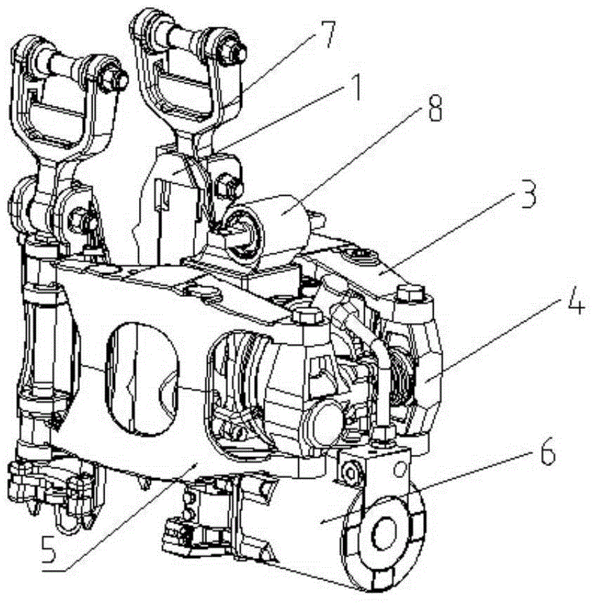
[0067] The rail locomotive vehicle brake caliper unit of this embodiment has a spring parking brake cylinder 6, and adopts a three-point hoisting installation form. There are hanging points 8 on it.
[0068] Others are the same as embodiment 2.
PUM
 Abstract
Description
Claims
Application Information