

Side exhaust electromagnetic relief valve weldforged valve body structure
A pressure relief valve and valve body technology, applied to the valve shell structure, valve details, valve device, etc., can solve the problems of large opening and closing pressure difference, difficulty in disassembly and assembly, leakage of packing and gasket, etc., and achieve the speed of opening and closing valve Improve and ensure the effect of manufacturing quality and good structural stability
- Summary
- Abstract
- Description
- Claims
- Application Information
AI Technical Summary
Problems solved by technology
Method used
Image

Examples
Embodiment 1
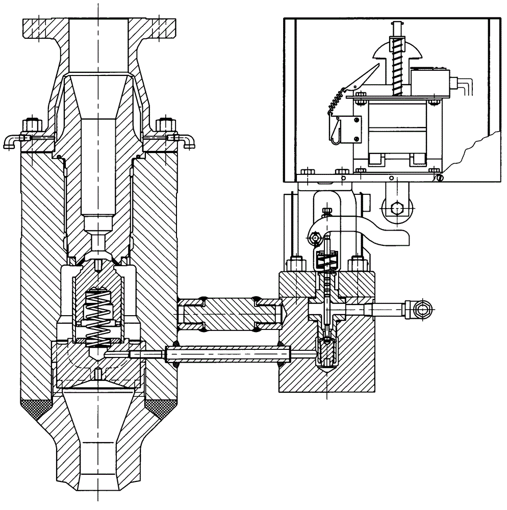
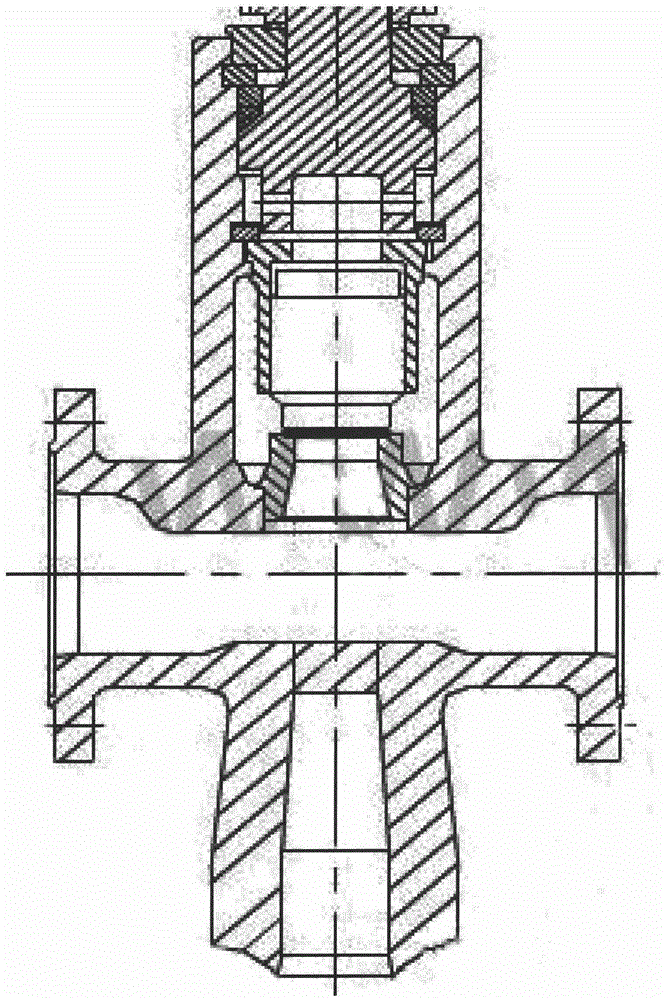
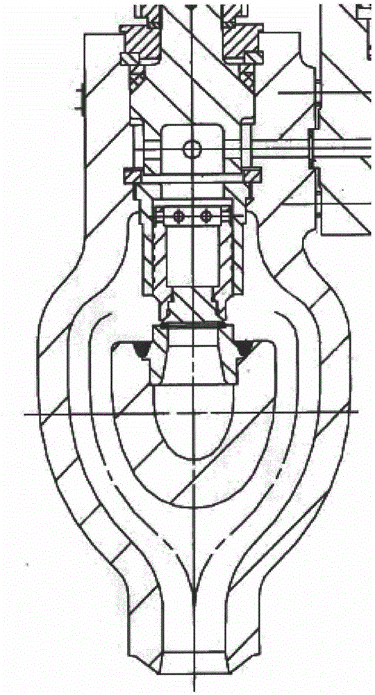
[0031] Such as Figure 4 , Figure 5 , Image 6 The forged-welded valve body shown is a double-sided exhaust structure with medium outlet ports on the left and right sides. The valve body flow channel structure is: from the lower side of the medium inlet end upward, through the side channels on the front and rear sides into the valve body In the middle chamber, when the steam is discharged from the middle through hole of the valve seat located on the lower side of the middle chamber of the valve body, the steam is diverted to the left and right sides to the outlet of the medium, through the exhaust elbow connected to the outlet flange and Upright exhaust pipe to a safe place.
[0032] The specific structure of this embodiment is as follows: the lower part of the forged-welded valve body is the installation and connection end of the valve. When the flange connection installation mode is used to connect, a connecting flange needs to be arranged and processed at the lower end ...
Embodiment 2
[0044] In the technical solution of the forged-welded valve body of this embodiment, only the specific implementation structure of the side plate (5) is different from that of Embodiment 1, and there is no difference in the structure of the other parts, so this embodiment only focuses on the side plate (5) The specific structure of the embodiment will be discussed, and the rest of the same place as the first embodiment will not be described.
[0045] Such as Figure 9 with Figure 10 As shown, the inner surface of the side plate (5) is different from the inner surface of the side plate (5) in Embodiment 1, which is only a simple middle plane plus the cylindrical surfaces on the lower two sides, the inner surface is concave, and the concave The middle part is also composed of a middle plane and a cylindrical surface that is connected with the upper and lower sides and bends inwardly. 5) The inner side surface is formed by scanning along the longitudinal path with a straight l...
PUM
 Abstract
Description
Claims
Application Information