Structure of side exhaust electromagnetic pressure relief valve for main steam system of power station

A main steam system, pressure relief valve technology, applied in the valve shell structure, lift valve, balance valve and other directions, to achieve the effect of convenient grinding, good structural stability, and the height of the middle cavity is reduced

Active Publication Date: 2018-05-01
DIANJIAN VALVE GRP CO LTD
View PDF6 Cites 0 Cited by
  • Summary
  • Abstract
  • Description
  • Claims
  • Application Information

AI Technical Summary

Problems solved by technology

[0008] In order to overcome the above-mentioned many inadequacies existing in the existing structure and technology, the present invention proposes a method that does not have oxidation and corrosion products entering the vicinity of the main valve disc sealing surface to affect the valve seal and condensation water to cause the sealing surface of the main valve and auxiliary valve. Leakage problem occurs, the height of the middle cavity of the valve body is greatly reduced, the sealing structure of the middle cavity is simplified, the sealing ability of the middle cavity is effectively improved, the processing and maintenance are convenient, the sealing surface of the main valve and the auxiliary valve has sufficient thermal compensation ability and better sealing Reliability, the sealing surface of the main valve disc has strong elastic compensation ability, the elastic deformation gap at the elastic tongue is not easy to be blocked, the opening and closing valve speed of the valve is increased, and the opening and closing pressure difference is reduced, and the spring is added in the main valve disc to It provides initial sealing ability and is beneficial to overcome jamming and assist valve clack closing to improve the reliability of the valve clack. The valve has better structural stability, less vibration and noise when discharging steam, and can operate in supercritical and ultrasuper The structure of the side exhaust electromagnetic pressure relief valve for the main steam system of the power station that is safely and reliably used on the critical unit

Method used


Image

  • Structure of side exhaust electromagnetic pressure relief valve for main steam system of power station
  • Structure of side exhaust electromagnetic pressure relief valve for main steam system of power station
  • Structure of side exhaust electromagnetic pressure relief valve for main steam system of power station

Examples


Embodiment 1

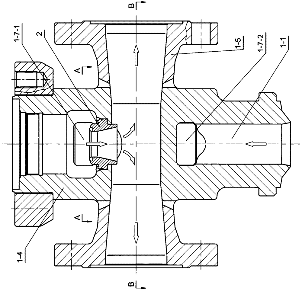
[0042] Such as Figure 5 and Figure 6 Shown is a schematic diagram of the product structure of the electromagnetic pressure relief valve of this embodiment. The electromagnetic pressure relief valve is used for supporting the main steam system of a 300MW subcritical unit, and the valve body is processed by WC9 casting.

[0043] The electromagnetic pressure relief valve adopts the integrated structural design of main valve and auxiliary valve. The pilot sealing structure of the auxiliary valve is arranged on the upper side of the main valve disc. The opening of the valve is driven by the driving device (17) driven by an electromagnet. The direction of the valve sealing surface is downward, the valve body (1) has a double exhaust structure with exhaust flanges (1-5) on both left and right sides, and the flow channel of the valve body is designed as: the inlet channel from the lower side The hole (1-1) goes upwards, bypasses the medium outlet channel hole on the lower side of t...

Embodiment 2

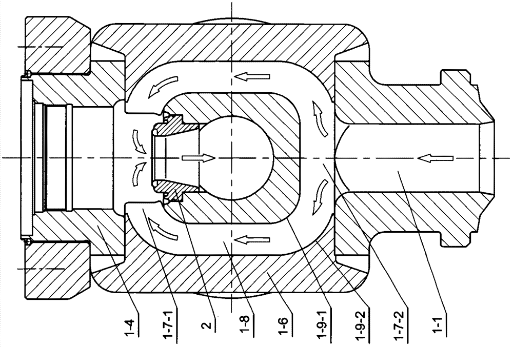
[0068] Such as Figure 13 Shown is a schematic diagram of the product structure of the electromagnetic pressure relief valve of this embodiment. The electromagnetic pressure relief valve is used for supporting the main steam system of a 1000MW ultra-supercritical thermal power unit, and the material of the valve body is F92 forged steel. The driving device (17) configured on the upper part of the valve can be a driving device provided by an electromagnet, or a driving device controlled by a solenoid valve to control a pneumatic mechanism to provide an active force; when the valve exhausts steam, the driving device (17) passes through The push rod on the lower side drives the valve stem (9) to open the valve.

[0069] The technical scheme of the valve structure of the electromagnetic pressure relief valve of this embodiment, only the specific implementation structure adopted by the valve body (1) is different from that of Embodiment 1. The valve body (1) of this embodiment adop...


PUM


Abstract

The invention discloses a side-exhaust steam electromagnetic pressure relief valve structure for the main steam system of a power station. It is composed of the outer disc, and the upper side of the sealing surface is provided with an elastic gap composed of a cone surface. There is also an elastic groove on the conical surface of the hot valve disc, and a number of small holes are drilled outward at the elastic groove. The lower end of the outer disc is in the There is an anti-seize edge protection near the outer side of the sealing surface, and a thermal compensation groove and a condensate storage structure are provided for the auxiliary valve seal. The body and cover adopt multiple combined sealing structures. The escape structure, the column adopts the heat dissipation column, and the flow channel structure is optimized. Its advantages: the sealing performance of the main and auxiliary valves has been significantly improved, the elastic gap is not easy to be blocked, the height of the middle cavity is reduced, the maintenance is convenient, the sealing of the middle cavity is good, the speed of the switching valve is increased, the valve work is safer and more reliable, and the vibration and vibration during discharge There is less noise.

Description

technical field [0001] The invention relates to a valve structure, in particular to a product structure of a side exhaust electromagnetic pressure relief valve used in the main steam system of a power station. Background technique [0002] The electromagnetic pressure relief valve is an important safety pressure relief valve, which is used to quickly open and discharge steam when the pressure of the main steam (superheated steam) of the power station exceeds the specified value, so as to avoid the action of the spring safety valve of the main steam system as much as possible, so as to maintain the pressure of the main steam The performance and reliability of the safety valve, prolonging the use and maintenance cycle of the main steam safety valve, and maintaining sufficient safety assurance capabilities for the unit are important supporting valves and key valves for thermal power units. At present, the safety pressure relief valves used in the main steam system of thermal po...

Claims


Application Information

Patent Timeline
Patent Type & Authority Patents(China)
IPC IPC(8): F16K17/04F16K1/36F16K27/02F16K27/08F16K47/02F16K49/00
CPCF16K1/36F16K17/0433F16K17/0466F16K27/0254F16K27/08F16K47/02F16K47/04F16K49/00
Inventor 章华
Owner DIANJIAN VALVE GRP CO LTD
Why Eureka
Try Eureka