Forged welding valve body structure of side exhaust electromagnetic pressure relief valve

A pressure relief valve, valve body technology, applied in the valve shell structure, valve details, valve device and other directions, can solve problems such as large opening and closing pressure difference, packing and gasket leakage, disassembly and assembly difficulties, etc., to achieve the speed of opening and closing the valve Improved, good structural stability, simple and easy disintegration effect

Active Publication Date: 2017-07-18
TANGSHAN ZHENGFENG IRON & STEEL CO LTD
View PDF9 Cites 0 Cited by
  • Summary
  • Abstract
  • Description
  • Claims
  • Application Information

AI Technical Summary

Problems solved by technology

The safety pressure relief valve with pneumatic quick-opening hard-sealed ball valve structure has also exposed many problems in a large number of uses, such as: the tungsten carbide coating on the ball and valve seat is easy to fall off, resulting in serious internal leakage and jamming; the ball and seat It is difficult to repair after the coating is scratched or peeled off, and the replacement cost of spare parts is high; there is still a big gap between the opening and closing speed of the pneumatically driven main valve and the electromagnetically driven auxiliary valve, resulting in low working sensitivity of the valve and low opening and closing pressure. The difference is large; the packing and gasket are prone to leakage due to the influence of high temperature and high pressure medium
The use of the product is also worrying, and sometimes the problems and impacts on the operation and maintenance of the unit are even more serious than the pilot-operated electromagnetic pressure relief valve
[0005] Although the electromagnetic pressure relief valve with the main disc facing down, double-sided exhaust, and the integral design of the main and auxiliary valves has obvious advantages in product structure and performance, the cast steel valve body of the current product also has structural problems. Disadvantages: Due to the design of the sealing structure of the valve cavity, the height of the cavity of the valve body is too high, which not only makes the processing of the valve cavity and the welding and grinding of the valve seat more difficult, it is not conducive to ensuring the manufacturing quality of the valve, but also makes the maintenance time It is difficult to disassemble and assemble, and the disassembly of the valve requires a lot of work and takes a long time
[0006] To sum up, the current electromagnetic pressure relief valves for large-capacity thermal power units have many defects in use due to the structural design and manufacturing reasons of the products, which have brought adverse effects on the safe operation of thermal power units and the use and maintenance of equipment.

Method used


Image

  • Forged welding valve body structure of side exhaust electromagnetic pressure relief valve
  • Forged welding valve body structure of side exhaust electromagnetic pressure relief valve
  • Forged welding valve body structure of side exhaust electromagnetic pressure relief valve

Examples


Embodiment 1

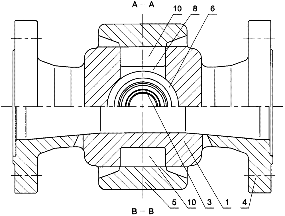
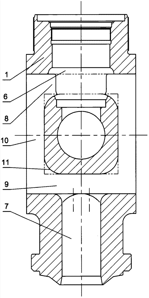
[0031] Such as Figure 4 and Figure 5 , Figure 6 , Figure 7 The forged-welded valve body shown is a double-sided exhaust structure with medium outlet ports on the left and right sides. The valve body flow channel structure is: from the lower side of the medium inlet end upward, through the side channels on the front and rear sides into the valve body In the middle chamber, when the steam is discharged from the middle through hole of the valve seat located on the lower side of the middle chamber of the valve body, the steam is diverted to the left and right sides to the outlet of the medium, through the exhaust elbow connected to the outlet flange and Upright exhaust pipe to a safe place.

[0032] The specific structure of this embodiment is as follows: the lower part of the forged-welded valve body is the installation and connection end of the valve. When the flange connection installation mode is used to connect, a connecting flange needs to be arranged and processed a...

Embodiment 2

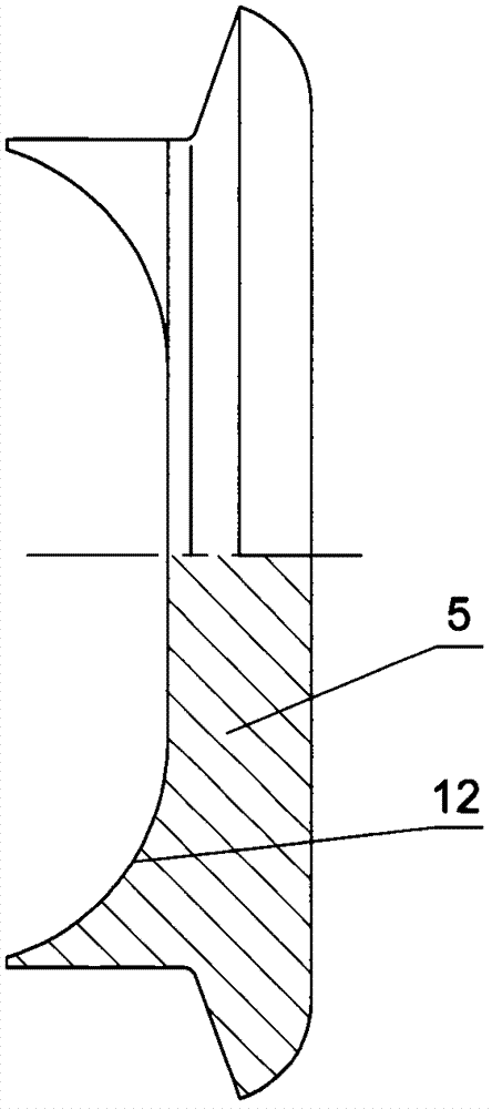
[0044] In the technical solution of the forged-welded valve body of this embodiment, only the specific implementation structure of the side plate (5) is different from that of Embodiment 1, and there is no difference in the structure of the other parts, so this embodiment only focuses on the side plate (5) The specific structure of the embodiment will be discussed, and the rest of the same place as the first embodiment will not be described.

[0045] Such as Figure 13 and Figure 14 , Figure 15 , Figure 16 As shown, the inner surface of the side plate (5) is different from the inner surface of the side plate (5) in Embodiment 1, which is only a simple middle plane plus the cylindrical surfaces on the lower two sides, the inner surface is concave, and the concave The middle part is also composed of a middle plane and a cylindrical surface that is connected with the upper and lower sides and bends inwardly. 5) The inner side surface is formed by scanning along the longitu...


PUM


Abstract

The invention discloses a side exhaust electromagnetic relief valve weldforged valve body structure. The weldforged valve body is in a double-side exhaust structure and is composed of a valve body portion, exhaust flanges of the left and right sides of the valve body portion and side plates of the front and rear sides of the valve body portion in a welded manner; the middle of the valve body portion is provided with exhaust holes transversely, horizontal communication holes are formed in the upper and lower sides of the front and rear sides, longitudinal communication grooves are formed among the horizontal communication holes, and the communication holes and the communication grooves are sealed through the side plates in a welded manner. The corners of the communication holes and communication grooves are rounded; the upper and lower portions of the side plates are provided with protrusion structures protruded towards the horizontal communication holes, and the protrusion structures are provided with arc surfaces. The structure has the advantages that the problem that tightness of the valve is affected by oxidation corrosion and condensation water is solved, the valve opening speed is increased, the open and close difference is decreased, the stability is improved, the height of the middle cavity of the valve body is decreased, machining and maintenance are facilitated, and higher safety and reliability of the valve are improved when the structure is used in the ultra (ultra) critical condition.

Description

technical field [0001] The invention relates to a valve structure, in particular to a structure form of a valve body of a side exhaust electromagnetic pressure relief valve used in a main steam system of a power station. Background technique [0002] Electromagnetic pressure relief valve is an important safety pressure relief valve for the main steam (superheated steam) system of the power station. As the pre-opening valve of the main steam safety valve, the electromagnetic pressure relief valve is used to quickly and automatically open and discharge steam when the pressure of the main steam (superheated steam) of the power station exceeds the specified value, so as to avoid the action of the main steam safety valve as much as possible and reduce the number of actions of the safety valve , so as to maintain the performance and reliability of the main steam safety valve, prolong the use and maintenance cycle of the main steam safety valve, maintain sufficient safety assurance...

Claims


Application Information

Patent Timeline
Patent Type & Authority Patents(China)
IPC IPC(8): F16K27/10F16K27/02
CPCF16K27/02F16K27/10
Inventor 章华
Owner TANGSHAN ZHENGFENG IRON & STEEL CO LTD
Why Eureka
Try Eureka