

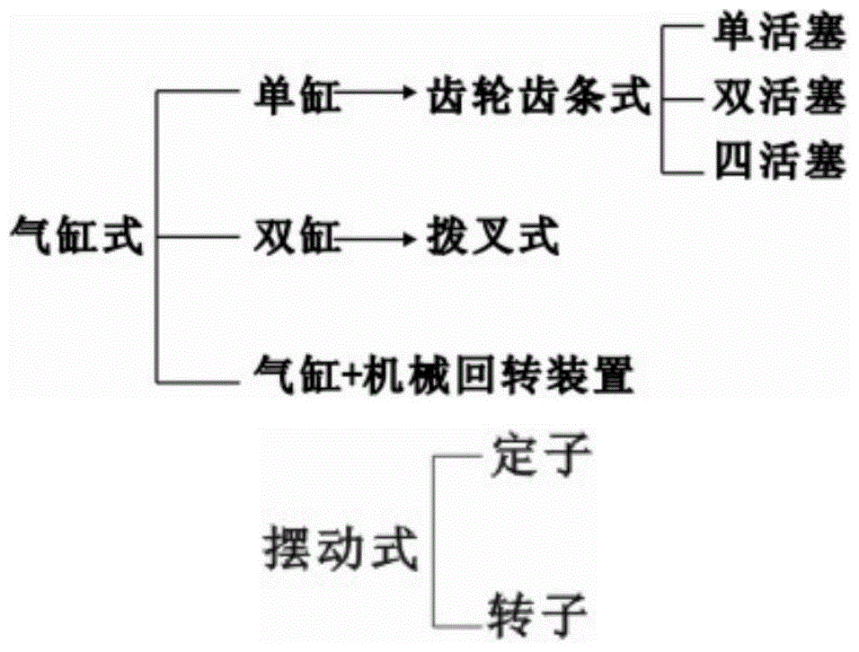
Dual-rotating-wedge speed-adjusting variable-pitch pneumatic valve actuator
A technology of pneumatic valves and actuators, applied in valve details, valve devices, engine components, etc., can solve problems such as excessive output torque margin, increased volume of pneumatic devices, valve and pipeline impact, etc., and achieves a simple and compact structure. , high positioning accuracy, small wear effect
- Summary
- Abstract
- Description
- Claims
- Application Information
AI Technical Summary
Problems solved by technology
Method used
Image

Examples
Embodiment Construction
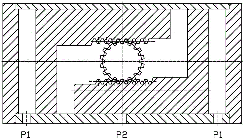
[0042] The technical solutions in the present invention will be clearly and completely described below in conjunction with the accompanying drawings in the present invention.
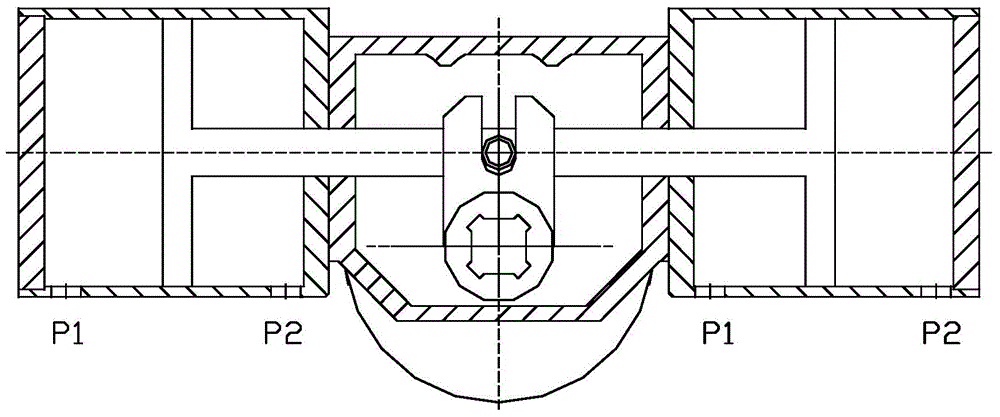
[0043] Please refer to Figure 7-9 One embodiment of the double-rotary wedge speed-adjustable variable-pitch pneumatic valve actuator of the present invention includes a housing and a main shaft 1 and a piston 11 arranged in the housing. The main shaft 1 is located in the middle of the housing, and the piston 11 is installed on the periphery of the main shaft 1. The piston 11 The axial up and down movement in the shell is realized by the air source pressure.
[0044]Described casing comprises the box body 15 that is positioned at the bottom and the box cover 4 that is positioned at the top, and inner and outer sealing ring (2,7,10,18) is housed on box body 15 and box cover 4, box body 15 and box cover 4 pass screw 21 is fixedly connected, and forms the support at both ends of the main shaft 1 through r...
PUM
 Abstract
Description
Claims
Application Information