Porous-medium radiation tube

A technology of porous medium and porous medium layer, applied in the field of radiant tubes, can solve the problems of high-grade energy consumption, limited air preheating temperature, consumption of high calorific value fuel, etc., so as to improve heat utilization efficiency, prolong service life, and increase surface temperature. Effect

Active Publication Date: 2015-03-25
SHENWU TECH GRP CO LTD
View PDF11 Cites 6 Cited by
  • Summary
  • Abstract
  • Description
  • Claims
  • Application Information

AI Technical Summary

Problems solved by technology

Although the above types of radiant tubes are relatively mature in technology, they all have certain limitations and deficiencies.
[0003] Among them, the load control of the electric radiant tube is relatively free, but it needs to consume high-grade energy, so the cost of the electric radiant tube is high, and it is not suitable for large-scale industrial applications
[0004] The load control of the conventional gas radiant tube is also relatively free, and the combustion is stable, but it needs to consume fuel with high calorific value, and at the same time, the exhaust gas temperature is high (the exhaust gas temperature is the temperature of the combustion flue gas), the thermal efficiency is low, and it is easy to generate local high temperature. The unevenness of the surface temperature is high, and the generated nitrogen oxides exceed the standard
[0005] The structure of the self-preheating radiant tube is relatively complicated, so the manufacturing cost and failure rate are high, the air preheating temperature is limited, and the exhaust gas temperature is still not lower than 500°C
[0006] The regenerative radiant tube solves the problems of high exhaust gas temperature and high uneven surface of the radiant tube, but when using low calorific value gas such as blast furnace gas, the range of heating temperature is limited
And when blast furnace gas is used below 650°C, the safety is not high, and high calorific value gas must be used as an open flame, which increases the instability of the system

Method used


Image

  • Porous-medium radiation tube

Examples


Embodiment Construction

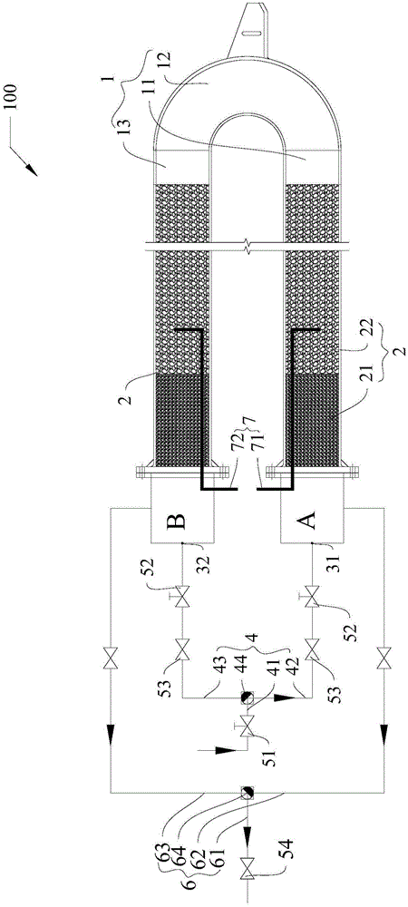
[0037] Embodiments of the present invention are described in detail below, examples of which are shown in the drawings, wherein the same or similar reference numerals designate the same or similar elements or elements having the same or similar functions throughout. The embodiments described below by referring to the figures are exemplary and are intended to explain the present invention and should not be construed as limiting the present invention.

[0038] In the description of the present invention, it should be understood that the orientation or positional relationship indicated by the terms "length", "inner" and "outer" are based on the orientation or positional relationship shown in the accompanying drawings, and are only for the convenience of describing the present invention and simplified descriptions, rather than indicating or implying that the device or element referred to must have a specific orientation, be constructed and operate in a specific orientation, and thu...


PUM


Abstract

The invention discloses a porous-medium radiation tube. The porous-medium radiation tube comprises a tube body, a gas supply tube component, an ignitor and a smoke discharge tube component. The tube body comprises a first part, a second part and a third part, and porous media are filled in the first part and the third part respectively. The gas supply tube component is communicated with the first part and the third part respectively and supplies mixed gas to the first part and the third part alternatively. The smoke discharge tube component is communicated with the first part and the third part respectively. When the gas supply tube component supplies the mixed gas to one of the first part and the third part, smoke generated can be partially discharged from the other one of the first part and the third part not communicated with the smoke discharge tube component. According to the porous-medium radiation tube, pollutants can be reduced, heat utilization efficiency of fuel burning is improved, non-uniformity of surface temperature of the tube body is reduced, service life of the porous-medium radiation tube is prolonged, electrodeless and continuous adjustability of heat load is realized, and the porous-medium radiation tube can be suitable for low heat.

Description

technical field [0001] The invention relates to a radiation tube, in particular to a porous medium radiation tube. Background technique [0002] Radiant tubes disclosed in the related art mainly include electric radiant tubes, conventional gas radiant tubes, self-preheating radiant tubes, regenerative radiant tubes, and various types of radiant tubes derived from these basic forms. Although the above types of radiant tubes are relatively mature in technology, they all have certain limitations and deficiencies. [0003] Among them, the load control of the electric radiant tube is relatively free, but it needs to consume high-grade energy, so the cost of the electric radiant tube is high, and it is not suitable for large-scale industrial applications. [0004] The load control of the conventional gas radiant tube is also relatively free, and the combustion is stable, but it needs to consume fuel with high calorific value, and at the same time, the exhaust gas temperature is h...

Claims


Application Information

Patent Timeline
Patent Type & Authority Applications(China)
IPC IPC(8): F23D14/12F23D14/46
CPCF23D14/12F23D14/46F23D2203/002
Inventor 吴道洪王东方
Owner SHENWU TECH GRP CO LTD
Why Eureka
Try Eureka