
Liquid crystal display panel capable of switching viewing angle and drive method thereof

A technology of a liquid crystal display panel and a driving method, which is applied in the directions of static indicators, optics, instruments, etc., can solve the problem that the size and energy consumption of the liquid crystal display panel cannot meet the requirements of portable electronic equipment, and increase the manufacturing cost, thickness and energy consumption of the liquid crystal display panel. and other problems, to achieve the effect of reducing manufacturing cost and energy consumption, convenient operation, and reducing thickness

Active Publication Date: 2015-03-25
TCL CHINA STAR OPTOELECTRONICS TECH CO LTD
View PDF4 Cites 30 Cited by
  • Summary
  • Abstract
  • Description
  • Claims
  • Application Information

AI Technical Summary

Problems solved by technology

This method will also increase the manufacturing cost, thickness and energy consumption of the LCD panel
[0008] Obviously, the above-mentioned liquid crystal display panels cannot meet the requirements of portable electronic devices in terms of size and power consumption

Method used


Image

  • Liquid crystal display panel capable of switching viewing angle and drive method thereof
  • Liquid crystal display panel capable of switching viewing angle and drive method thereof
  • Liquid crystal display panel capable of switching viewing angle and drive method thereof

Examples


Embodiment Construction

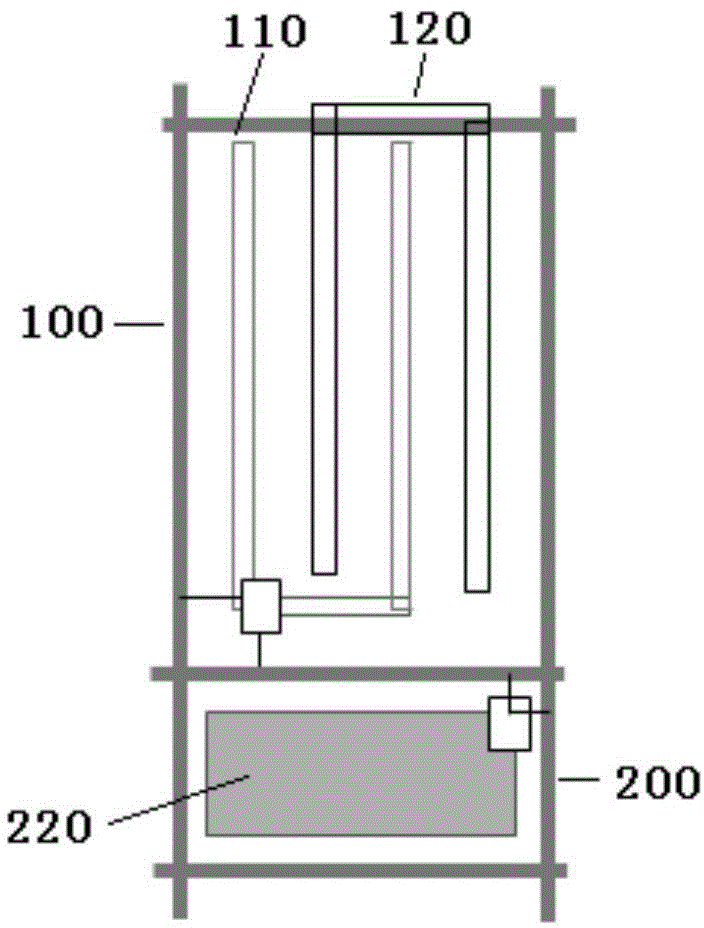
[0038] The present invention is based on the technology of hybrid light distribution. In order to make the objectives, technical solutions and advantages of the present invention clearer, the present invention will be further described in detail below with reference to the accompanying drawings.

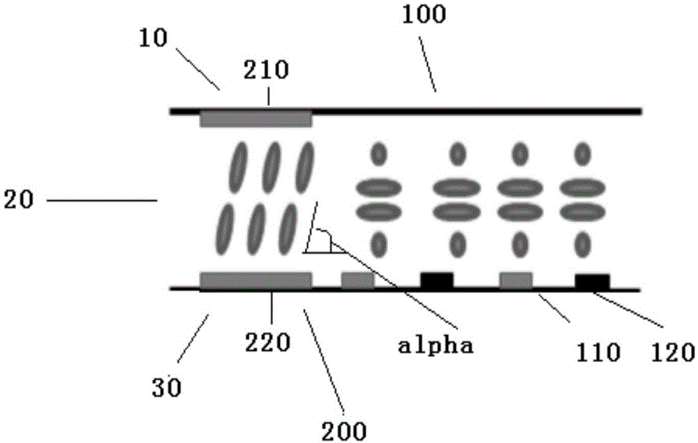
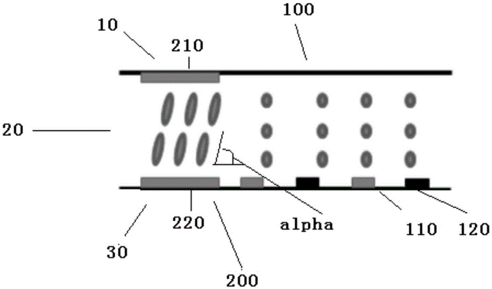
[0039] Combine below figure 1 ~ Figure 3 illustrates this method in detail.

[0040] figure 1 A top view of a part of the display area of ​​the liquid crystal display panel of the first embodiment of the present invention is shown. As in the prior art, the panel includes an upper substrate 10 and a lower substrate 20 arranged parallel to each other, and a liquid crystal layer 30 arranged between the upper substrate 10 and the lower substrate 20, preferably a negative liquid crystal material.

[0041] In this embodiment, the upper substrate 10 may include an upper substrate glass layer, an upper substrate quarter-wave plate, an upper substrate half-wave plate, and an upper substrate polarize...


PUM


Abstract

The invention discloses a liquid crystal display panel capable of switching the viewing angle and a drive method of the liquid crystal display panel. A pixel unit of a liquid crystal display panel display region comprises a primary pixel region and a secondary pixel region; the primary pixel region is homogeneous alignment and arranged in the primary pixel region, and a lower substrate is provided with pixel electrodes and public electrodes at intervals; the secondary pixel region is homeotropic alignment and arranged in the secondary pixel region, and an upper substrate and the lower substrate are correspondingly provided with an upper substrate electrode and a pixel electrode respectively. When no bias voltage is applied on the upper substrate electrode of the secondary pixel region, the liquid crystal molecules corresponding to the secondary pixel region do not defect, and the large viewing angle of the secondary pixel region leaks light, narrow viewing angle display is achieved; when the bias voltage is applied on the upper substrate electrode of the secondary pixel, the liquid crystal molecules corresponding to the secondary pixel region deflect to the plane-on state, the large viewing angle of the secondary pixel region does not leak the light any more, and wide-view-angle display is achieved.

Description

Technical field [0001] The present invention relates to liquid crystal display technology, in particular to a liquid crystal display panel with a switchable viewing angle and a driving method thereof. Background technique [0002] The viewing angle range (referred to as viewing angle) is an important performance index of the liquid crystal display panel. The liquid crystal display panel needs to change the polarization state of the transmitted light by adjusting the arrangement of the liquid crystal molecules to realize the display function. Therefore, due to the influence of the optical anisotropy of the liquid crystal molecules, the viewing angle of the liquid crystal display is smaller than that of the cathode ray tube display. With the continuous development of technology, in order to increase the viewing angle of liquid crystal displays, vertical alignment (VA) mode, pattern vertical alignment (PVA) mode, multi-chip vertical alignment (MVA) mode, in-plane switching (IPS) mo...

Claims


Application Information

Patent Timeline
Patent Type & Authority Applications(China)
IPC IPC(8): G02F1/1343G02F1/133G02F1/139
CPCG02F1/13306G02F1/134309G02F1/134363G02F1/134372G02F1/134381G02F1/1323G02F1/133753G02F1/13439G02F2413/04G02F2413/06G02F1/133638G02F1/133757G02F1/134345G02F1/133711
Inventor 唐岳军
Owner TCL CHINA STAR OPTOELECTRONICS TECH CO LTD
Learn More