
Dual-mode display device and method for projector

A technology for a projector and a driving device, which is applied to lighting devices, projection devices, components of lighting devices, etc., can solve the problems of indistinct colors, low monochrome intensity, and yellowishness, and achieve the effect of increasing convenience.

Inactive Publication Date: 2015-03-25
WUXI SEEMILE LASER DISPLAY TECH
View PDF12 Cites 5 Cited by
  • Summary
  • Abstract
  • Description
  • Claims
  • Application Information

AI Technical Summary

Problems solved by technology

[0004] With the current technology, since the angle of the color wheel and the rotation direction of the motor are fixed, if the projector wants to produce a high-brightness mode, it must increase the yellow angle in a large area. Although the brightness can be greatly increased, the color must not be changed. Bright, the overall picture will be yellowish. If you use this color wheel angle to adjust the more vivid mode, use the principle of adjusting the current to reduce the current through the area that will greatly increase the brightness. This will cause a big problem that is a color. The angle of the wheel is 360 degrees. If the current is reduced in the area where the brightness is greatly increased, there will be a small area left in the area with a relatively pure color. In this way, the overall brightness of the bright mode will be much lower, and the intensity of the monochrome will be much lower. It will also be very low because the color wheel angle is not large enough

Method used


Image

  • Dual-mode display device and method for projector
  • Dual-mode display device and method for projector
  • Dual-mode display device and method for projector

Examples


Embodiment Construction

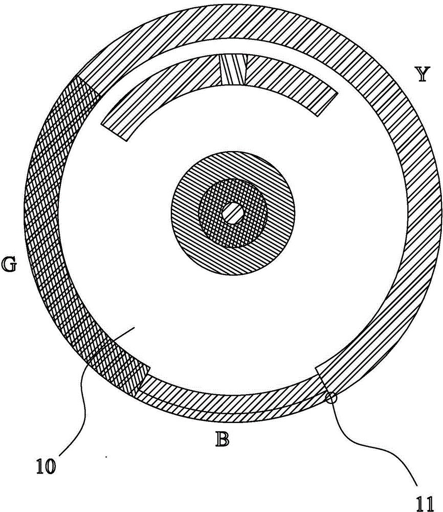
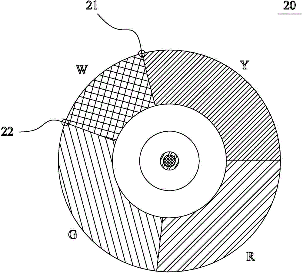
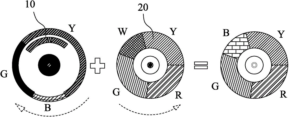
[0026] Please refer to figure 1 and figure 2 as shown, figure 1 It is a schematic diagram of the enlarged structure of the fluorescent wheel in the embodiment of the present invention; figure 2 It is a schematic diagram of the enlarged structure of the color wheel in the embodiment of the present invention. A dual-mode display device for a projector at least includes a rotatable fluorescent wheel 10, a first driving device (not shown in the figure) for rotating the fluorescent wheel, a rotatable color wheel 20, and a first driving device for rotating the color wheel 20. Two driving devices (not shown in the figure), the fluorescent wheel 10 has a plurality of color segments yellow Y, green G, and blue B, and is distributed in a ring shape, and the color wheel 20 has a plurality of colors distributed in a ring shape The optical filters are distributed along the circumferential direction on the disk surface of the color wheel 20, of course, other distribution methods can al...


PUM


Abstract

The invention discloses a dual-mode display device and method for a projector. The device comprises a rotatable fluorescent wheel, a first drive device, a color wheel and a second drive device. The fluorescent wheel is provided with a plurality of fluorescence color sections. The color wheel is provided with a light filter in multiple colors. The second drive device is a bidirectional drive mechanism driving the color wheel to rotate clockwise and counterclockwise. The device further comprises a starting point recording device. When the color wheel rotates counterclockwise to enable the projector to present a high-brightness mode, the color wheel rotates clockwise to enable the projector to present a bright mode; when the color wheel rotates clockwise to enable the projector to present the high-brightness mode, the color wheel rotates counterclockwise to enable the projector to present the bright mode. According to the dual-mode display device and method, clockwise rotation and counterclockwise rotation of the color wheel are utilized, so two architectures of the high-brightness mode and the bright mode can be produced on the same projector at the same time; the situation that the cost is increased due to the requirement for different color wheels will not happen; moreover, people do not need to worry about the fact that sometimes a high-brightness projector is needed while sometimes a projector with a bright color function is needed, and life convenience is added.

Description

technical field [0001] The present invention relates to the technology in the field of optical projection equipment, in particular to a dual-mode display device and a display method for a projector. Background technique [0002] Current projectors are nothing more than three kinds of light sources: 1. Mercury lamp 2. LED 3. Laser, this patent is applicable to various projectors that need two-color wheels. The laser projector is a relatively new technology at present. The principle of the light source is to use the array of multiple blue lasers to focus the light on the fluorescent wheel through the lens group. (Lambertian body) After reflection, it then passes through the lens group and the color wheel to refocus the light at the entrance of the light guide. The laser projector produces color by using the fluorescent powder on the fluorescent wheel to convert the blue laser light excitation into other red, green and yellow light, and then use the color wheel to excite the l...

Claims


Application Information

Patent Timeline
IPC IPC(8): G03B21/14
CPCF21V9/40G02B26/008G03B21/14
Inventor 林明德叶文彬徐尉彬
Owner WUXI SEEMILE LASER DISPLAY TECH
Learn More