Interactive welding joint groove graph drawing and parameter tagging method

A technology for welding joints and graphic drawing, which is used in electrical digital data processing, special data processing applications, instruments, etc., can solve problems such as low efficiency, information isolation, and distortion, and achieve the effect of avoiding graphic distortion.

Inactive Publication Date: 2015-03-25
泰州学院
View PDF0 Cites 9 Cited by
  • Summary
  • Abstract
  • Description
  • Claims
  • Application Information

AI Technical Summary

Problems solved by technology

Judging from the current research status at home and abroad, there are mainly two methods for joint graphic expression: the first method is to use bitmaps to describe joint information and groove parameters. This method requires a large number of enumerations due to different combinations of groove types and parameters Joint groove bitmap, the reason is that the groove parameters cannot be marked and modified in time in the bitmap, the efficiency is low, and when embedded into the output process report document, distortion may occur with the change of the bitmap display area; The second method is to use a third-party vector graphics drawing platform. After drawing the joint bevel graphics, use OLE (object linking and embedding, object linking and embedding) technology to import to the process design platform, and then return to vector graphics drawing when modifying platform, this parasitic method is inconvenient when labeling groove parameters and graphics output, and at the same time, the parameter information marked cannot be conveniently used by other software modules, resulting in the isolation of information

Method used


Image

  • Interactive welding joint groove graph drawing and parameter tagging method
  • Interactive welding joint groove graph drawing and parameter tagging method
  • Interactive welding joint groove graph drawing and parameter tagging method

Examples


Embodiment Construction

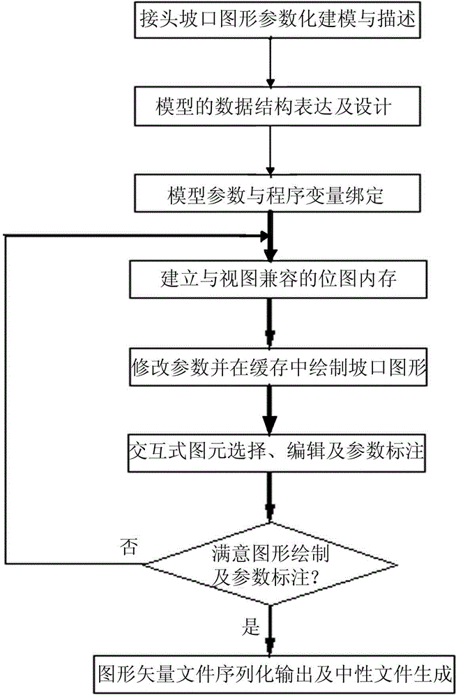
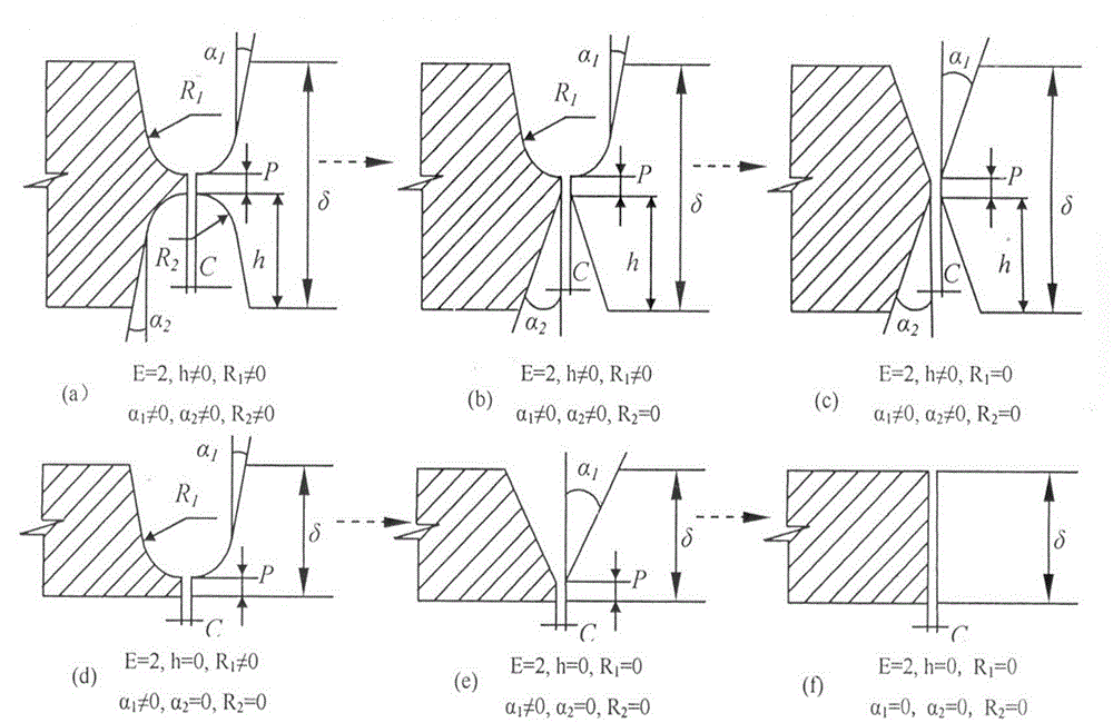
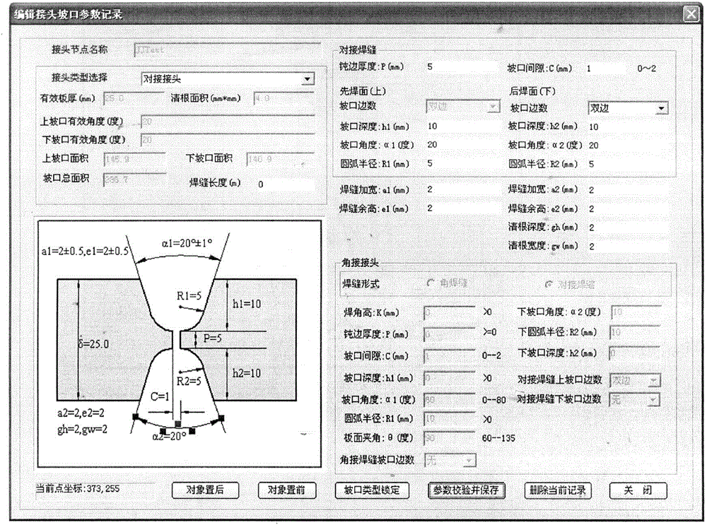
[0028] exist figure 1 Among them, the present invention provides an interactive welding joint groove pattern drawing and parameter labeling method, which includes the following steps: Step 1, first parametrically modeling the groove pattern, its main steps: 1a: analyzing commonly used grooves The shape characteristics of the type, on the basis of keeping the topological structure of the groove graph unchanged, classify the common types of welded joints; 1b: Parametric description and model representation of the joint groove graph, using the idea of ​​variant design to realize the groove graph It evolves into different groove graphics with parameter changes, reflecting the shape evolution of groove graphics with parameter changes; 1c: Establish the binding of groove model parameters and program variables, and dynamically modify the groove model parameters through the value and change of variables to achieve The geometric shape and size of the graphics can be changed to realize...


PUM


Abstract

The invention discloses an interactive welding joint groove graph drawing and parameter tagging method. The method comprises the following steps of (1) conducting parametric modeling on a groove graph; (2) establishing an interactive graphic element construction and parameter tagging method; (3) after the groove graph is drawn, storing joint groove parameter information and the groove graph in a database table field through database metadata, and storing the groove graph into a database in a neutral meta file vector format WMF. On the one hand, the size of a graph file is reduced, meanwhile, the vector graph file is loaded into an application program, and parameter tagging and graph property modification can be carried out on the vector graph file to achieve graph data reuse; on the other hand, the neutral groove graph file can be used as an embedded graph object to be output to a process report file, sawteeth or graphic element interruption and other distortion phenomena will not be generated during stepless zooming in a display area, and the graph file has the advantages in the aspects of storage and display compared with a bitmap file.

Description

technical field [0001] The invention relates to an interactive welding joint groove graph drawing and parameter labeling method. Background technique [0002] Welding process informatization is an inevitable link in the development of intelligent welding. The information expression and organization of welding joint process is an extremely important initial step. Its content includes base metal information, welding process electrical parameters and pre-welding, welding process and post-welding In addition to the detection information, it also includes joint graphic information reflecting the joint form and groove geometric parameters, and information representing the weld bead process graphics during the welding process, among which the description, organization and processing of the groove graphic information is the key to the welding process design process. Key points and difficult points. Judging from the current research status at home and abroad, there are mainly two me...

Claims


Application Information

Patent Timeline
Patent Type & Authority Applications(China)
IPC IPC(8): G06F17/50
Inventor 沈春龙
Owner 泰州学院
Why Eureka
Try Eureka