
Low-inductance power capacitor
A technology of power capacitors and capacitors, which is applied to the terminals of fixed capacitors and parts of fixed capacitors, etc., which can solve problems such as damage to absorption capacitors and affect the normal operation of equipment, and achieve reduced self-inductance, uniform heat dissipation, and short current flow paths Effect
- Summary
- Abstract
- Description
- Claims
- Application Information
AI Technical Summary
Problems solved by technology
Method used
Image

Examples
Embodiment Construction
[0014] The technical solutions in the embodiments of the present invention are clearly and completely described below in conjunction with the accompanying drawings. Apparently, the described embodiments are only some of the embodiments of the present invention, but not all of them. Based on the embodiments of the present invention, all other embodiments obtained by persons of ordinary skill in the art without making creative efforts belong to the protection scope of the present invention.
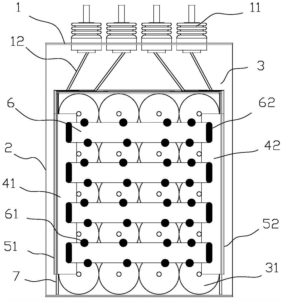
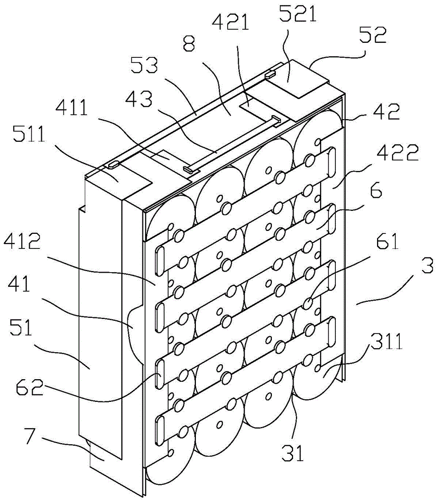
[0015] Such as figure 1 As shown, the present invention includes a cover plate assembly 1 , a casing 2 and a capacitor core group 3 fixed in the casing 2 . One or more capacitor core groups 3 can be arranged side by side, and the outside of each capacitor core group 3 is wrapped with an insulating film and placed in the casing 2, and the insulating film is placed on the figure 1 is not drawn in. The positive and negative poles of the capacitor core group 3 are electrically connected to t...
PUM
 Abstract
Description
Claims
Application Information