A dry film sticking machine and a dry film sticking method

A dry film sticking machine and dry film sticking technology, which is applied in the direction of electrical components, semiconductor/solid-state device manufacturing, circuits, etc., can solve the problems of manpower consumption and deviation, and achieve the effects of reducing labor costs, precise time control, and avoiding mistakes

Active Publication Date: 2017-11-07
NANTONG FUJITSU MICROELECTRONICS
View PDF4 Cites 0 Cited by
  • Summary
  • Abstract
  • Description
  • Claims
  • Application Information

AI Technical Summary

Problems solved by technology

[0004] In order to overcome the problems of manpower consumption and large deviation in the time control of the dry film sticking process in the prior art, the present invention provides a dry film sticking machine and a film sticking method thereof

Method used


Image

  • A dry film sticking machine and a dry film sticking method
  • A dry film sticking machine and a dry film sticking method
  • A dry film sticking machine and a dry film sticking method

Examples


Embodiment Construction

[0019] The present invention will be described in further detail below in conjunction with the accompanying drawings and embodiments. It should be understood that the specific embodiments described here are only used to explain the present invention, not to limit the present invention.

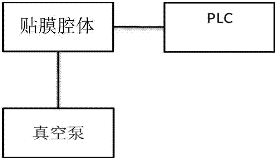
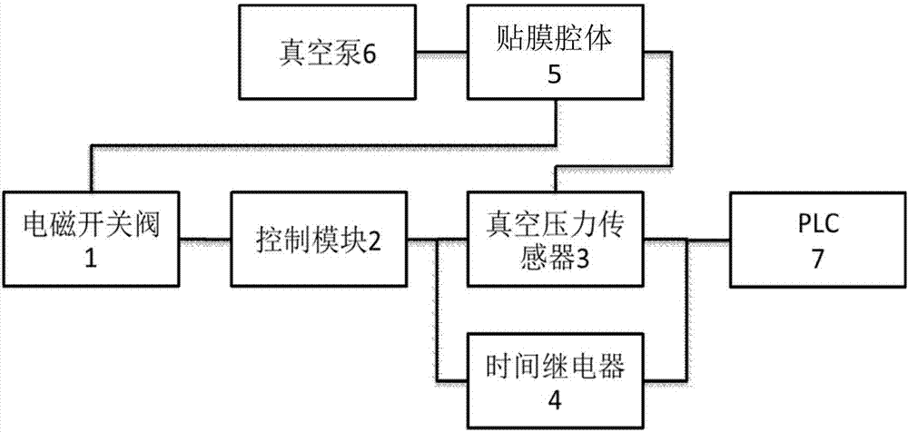
[0020] The first specific embodiment is as figure 2 As shown, this embodiment provides a dry film sticking machine, including a film sticking device, an electromagnetic switch valve 1, a control module 2, a vacuum pressure sensor 3, a time relay 4, a film sticking cavity 5, a vacuum pump 6, and a PLC7.

[0021] Wherein, the vacuum pump 6 is connected with the film sticking cavity 5 and is used for vacuumizing the film sticking cavity 5 . The vacuum pressure sensor 3 is arranged in or on the film sticking cavity 5 of the dry film sticking machine, and is used to measure the air pressure in the film sticking cavity 5 . The pressure of the vacuum pressure sensor 3 can be preset through an inpu...


PUM


Abstract

The invention provides a dry film sticking machine and a film sticking method thereof. The dry film sticking machine includes a vacuum pressure sensor (3), a time relay (4), and a PLC (7). When the vacuum degree in the film cavity (5) reaches a specific value SP1, the vacuum pressure sensor (3) transmits the vacuum degree signal SP1 to the PLC (7) and the time relay (4), and triggers the time relay (4) to start counting down, PLC (7) controls the film sticking device to start film sticking; the time relay (4) transmits a signal T to PLC (7) when the countdown ends; when PLC (7) receives the signal T, it controls the film sticking device to finish sticking the film and opens the film sticking cavity (5) . By using the time relay in the dry film sticking machine and dry film sticking work instead of manual timing to directly control the film sticking process time of the machine, the labor cost can be greatly reduced. At the same time, using the time relay to control the time can avoid errors and make the control more accurate than manually pinching the watch. Higher precision ensures that the process of the film laminating machine is consistent, and different process time settings can be made according to the characteristics of different materials.

Description

technical field [0001] The invention relates to the technical field of semiconductor packaging, in particular to a dry film sticking machine and a dry film sticking method. Background technique [0002] When pasting the dry film, first peel off the polyethylene protective film from the dry film, and then paste the dry film resist on the copper clad board under heat and pressure. The resist layer in the dry film becomes soft after being heated, and its fluidity increases, and the film is pasted by means of the pressure of the hot pressing roller and the action of the adhesive in the resist. The film sticking is usually done on a film sticking machine. There are many types of film sticking machines, but the basic structure is roughly the same. The main factors that affect the effect of film application are pressure, temperature and transmission speed, and these three factors are all affected by the film application time, so controlling the film application time is very import...

Claims


Application Information

Patent Timeline
Patent Type & Authority Patents(China)
IPC IPC(8): H01L21/56H01L21/67
Inventor 丁万春
Owner NANTONG FUJITSU MICROELECTRONICS
Why Eureka
Try Eureka