
LED constant current driver

A technology of constant current driver and converter, which is applied in the direction of conversion equipment, lighting devices, light sources, etc. without intermediate conversion to AC, to achieve the effect of eliminating loss

Inactive Publication Date: 2015-03-25
SHENZHEN KIWI MICROELECTRONICS CO LTD
View PDF6 Cites 18 Cited by
  • Summary
  • Abstract
  • Description
  • Claims
  • Application Information

AI Technical Summary

Problems solved by technology

[0010] Based on this, it is necessary to provide a new solution to the problems in the control design of the step-down converter circuit in the prior art

Method used


Image

  • LED constant current driver
  • LED constant current driver
  • LED constant current driver

Examples


Embodiment Construction

[0026] In order to save cost and improve the conversion efficiency of the system, the present invention proposes a method for realizing constant current control by sampling the inductance series impedance.

[0027] In order to make the purpose, features and advantages of the present invention more comprehensible, specific implementations of the present invention will be described in detail below in conjunction with the accompanying drawings.

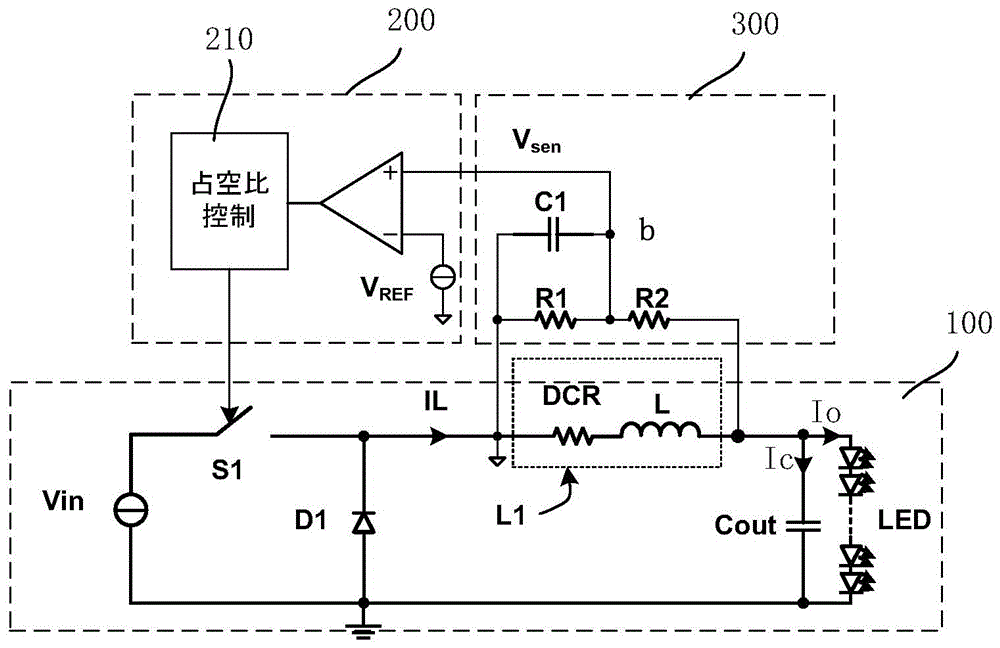
[0028] figure 2 Shown is the circuit structure of the constant current driver provided in this embodiment. Specifically, it includes a step-down converter unit 100 , a control circuit unit 200 and a sampling unit 300 . The sampling unit 300 is connected in parallel with the inductor L in the step-down converter unit 100 to sample the inductor current I passing through the inductor L L , and provide a feedback signal to the control circuit unit 200, the control circuit unit 200 according to the feedback signal and the reference voltage...


PUM


Abstract

The invention relates to an LED constant current driver. The LED constant current driver includes a step-down converter unit, a sampling unit and a control unit, wherein the step-down converter unit includes an inductor and a switch, the sampling unit is connected in parallel with the inductor and provides feedback signals, and the control unit comprises a reference voltage supplying end and controls the switch-on or switch-off of the switch through the feedback signals provided by the sampling unit and the difference value of reference voltage. According to the LED constant current driver provided by the technical scheme of the invention, a sampling resistor in a step-down converter unit in a traditional LED constant current driver is omitted, so that the loss of the sampling resistor, generated in the step-down converter unit, can be eliminated, and therefore, design cost of the step-down converter unit can be decreased, and conversion efficiency can be improved.

Description

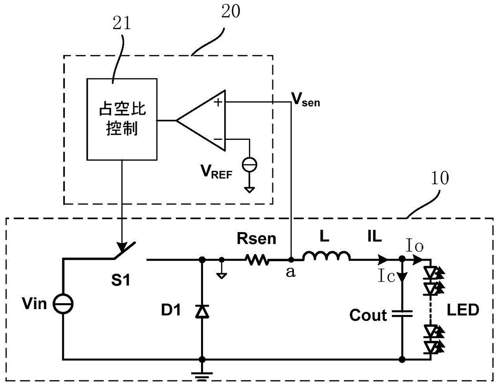
technical field [0001] The invention relates to an LED constant current driver. Background technique [0002] Since the step-down converter (Buck) circuit has the advantages of relatively good conversion efficiency and simple circuit structure, it is more and more used in the circuit design of non-isolated LED constant current drivers. [0003] figure 1 Shown is a circuit structure of a constant current driver in the prior art, which includes a step-down converter unit 10 and a control circuit unit 20 . Such as figure 1 As shown in , the step-down converter unit 10 includes an input voltage source Vin, a power switch S1, a semiconductor diode D1, an inductor L, an output capacitor Cout and a sampling resistor Rsen. The basic operating principle of the step-down converter is: [0004] During the on-time Ton, the power switch S1 is turned on, and the inductor L stores energy in the form of a magnetic field. As the input voltage source Vin charges the inductor L, an inducto...

Claims


Application Information

Patent Timeline
IPC IPC(8): H02M3/10H02M1/08H05B37/02
CPCH05B47/10
Inventor 裘卫红张波胡遇杰
Owner SHENZHEN KIWI MICROELECTRONICS CO LTD
Learn More