In-furnace retro-reflectors with steerable tunable diode laser absorption spectrometer

A retro-reflection, optical device technology, applied in the field of internal combustion characteristics, which can solve the problems of limited practicability of traditional systems

Active Publication Date: 2015-03-25
正点技术有限公司
10 Cites 0 Cited by

AI-Extracted Technical Summary

Problems solved by technology

[0004] Due to the cost and complexity of optics and corresponding furnace perforations, conventional systems are of limit...

Method used

[0074] Advantages of using retro-reflectors 42 include requiring fewer paths, thereby avoiding the complications of sloped paths in tightly packed furnaces. In addition, the laser beam 44 used to measure each cell must travel out and back, thereby doubling the path length ("two passes through the laser path") and increasing the absorption signal strength. Stronger absorption signals reduce the deleterious effects of noise sources such as modal, etalon, and detector noise. In additio...

Abstract

A method of monitoring combustion properties in an interior of a furnace is described. A beam of light is projected through a pitch optic including a pitch collimating lens residing outside the boiler interior. The pitch collimating lens projects the beam through a penetration into the boiler interior. The beam of light projected by the pitch collimating lens is reflected from at least one in-furnace retro-reflector, and received with a catch optic substantially identical to the pitch optic residing outside the boiler interior. The pitch optic and the catch optic may be embodied in the same pitch/catch optic. The pitch collimating lens may also be steered toward another of the at least one in-furnace retro-reflectors. Combustion properties may be calculated for each retro-reflector or based on retro-reflector zones within the furnace.

Application Domain

Fluid heatersAbsorption/flicker/reflection spectroscopy +4

Technology Topic

CombustionLight beam +4

Image

  • In-furnace retro-reflectors with steerable tunable diode laser absorption spectrometer
  • In-furnace retro-reflectors with steerable tunable diode laser absorption spectrometer
  • In-furnace retro-reflectors with steerable tunable diode laser absorption spectrometer

Examples

  • Experimental program(1)

Example Embodiment

[0043] Unless otherwise indicated, all numbers used in the specification and claims indicating the number of elements, sizes, reaction conditions, etc. are understood to be modified by the term "about" in all instances.
[0044] In this application and claims, unless specifically stated otherwise, the singular number used includes the plural number. In addition, the use of "or" means "and/or" unless stated otherwise. In addition, the use of the term "including" and other forms such as "includes" and "included" are not limiting. Also, unless specifically stated otherwise, terms such as "element" or "component" encompass both elements and components including one unit and elements and components including more than one unit.
[0045] US Patent No. 7,469,092, the entire content of which is hereby incorporated herein, discloses a method and apparatus for monitoring and controlling a type of combustion process that requires pipe elbows to be installed in the boiler wall to provide an optical entrance to the boiler. U.S. Patent No. 7,469,092 describes a sensing system that includes an auto-alignment feature that allows throwing and grasping optics to maintain optical alignment even if they are screwed to themselves easily move according to thermal effects or wind and vibration On the boiler or unfriendly processing room. The described system provides separate throwing and gripping optics including separate throwing and gripping collimating lenses mounted on a feedback controlled tilt table. The multiplexed light is emitted across the measurement area by a collimating throw lens directly attached to the input fiber, and a grasping collimator lens located at the opposite end of the measurement area optically couples the emitted light to the output fiber, which is usually a multimode fiber . As a result, the gripping optics must be oriented so that it is collinear with the light beam emitted from the throwing optics. This is necessary so that the focused emitted beam will reach the receiving core of the multimode fiber.
[0046] In the following, the terms "boiler" and "furnace" will be used interchangeably to refer to any combustion chamber where it is desired to monitor and control the combustion process.
[0047] Refer to Figure 1 to Picture 10 And compared to the system described in US Patent No. 7,469,092, the system according to various embodiments provides a combined throwing/grasping optics including a throwing/grasping collimator lens mounted on a feedback control tilt table. The multiplexed light is emitted across the measurement area by a collimating throw lens directly attached to the input fiber, and the collimating grab lens optically couples the emitted light to the output fiber, which is usually a multimode fiber. Here, the collimating throw lens and the collimating grab lens are implemented with the same collimating lens. The multiplexed light emitted across the measurement area is reflected back to the source by at least one retro reflector positioned in the furnace. A retroreflector is an optical device that redirects incident laser light back toward its source regardless of the angle of incidence, as long as the beam is incident on the entrance to the aperture of the retroreflector.
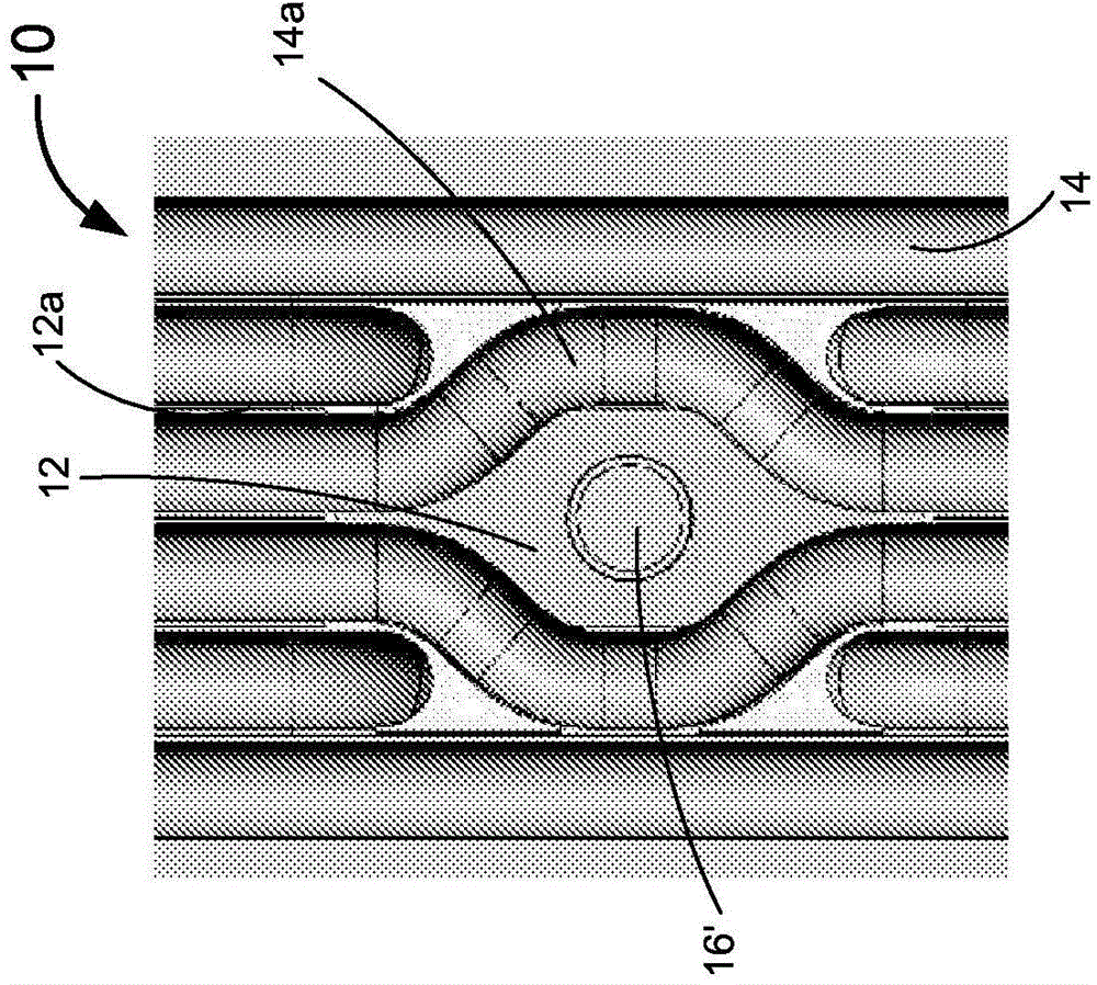
[0048] Figure 1A with Figure 1B Two examples of perforations 16 in the wall 12 of the furnace 10 for providing optical access to the inside of the furnace are shown. Figure 1A A boiler wall 12 is shown that includes a series of parallel steam tubes 14 separated by a plurality of metal films 12a. Such as Figure 1A As shown in the figure, the tube elbow 14a is provided to reroute the steam tube 14 around the perforation, which may be, for example, a 2" (5.08 cm) diameter circular perforation 16'.
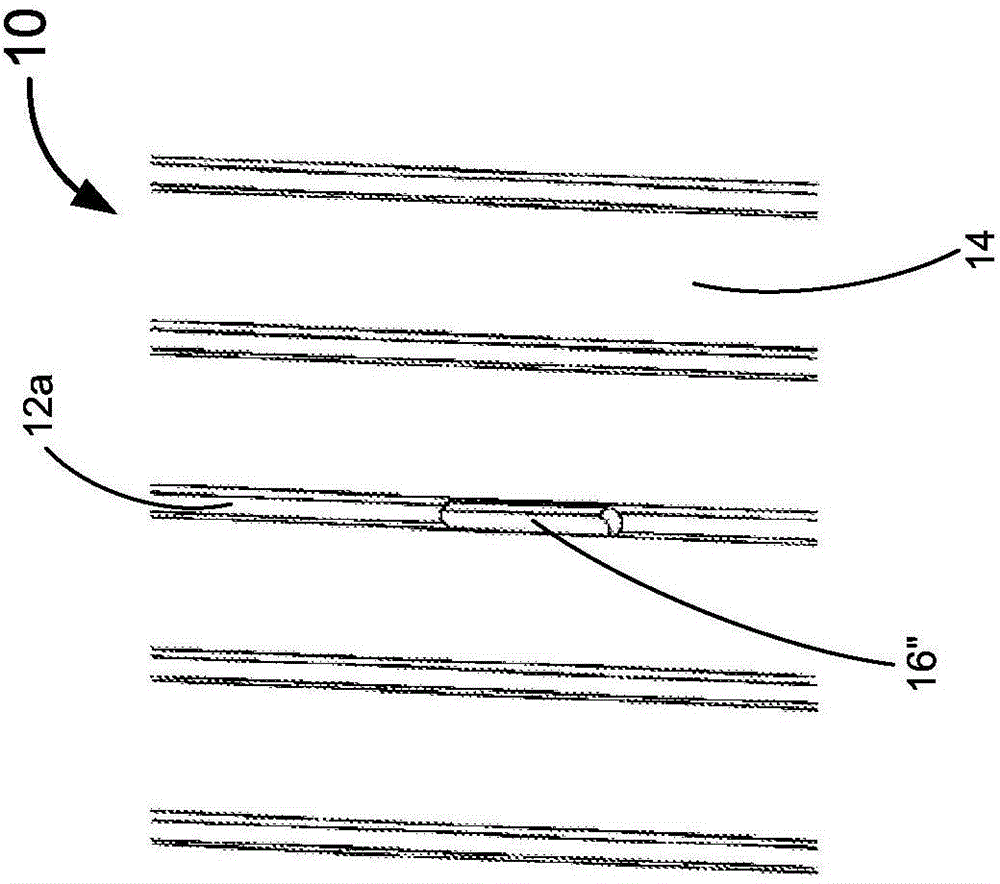
[0049] Figure 1B An alternative embodiment described in WO 2010/080892 A2 is shown, the entire content of which is incorporated herein. Figure 1B A slotted film perforation 16" with a width of approximately 1/2 inch (1.27 cm) (equal to the width of the film 12a) and elongated in a direction parallel to the steam pipe 14 is shown. This arrangement eliminates the need for the pipe elbow 14a (Such as Figure 1A Shown) need to promote light collection efficiency at the same time. However, alignment and maintaining alignment are better than Figure 1A The pipe elbow method shown is significantly more difficult when supporting a 2 inch (5.08 cm) circular perforation 16' and requires tighter alignment tolerances.
[0050] although Figure 1A with Figure 1B The embodiment shown in relates to a boiler having a steam tube in the wall of the boiler, but the embodiment is not limited to this, and can be applied to any combustion chamber where monitoring of combustion characteristics is desired. In this case, the shape of the perforation 16 can be any shape (including but not limited to circular, substantially circular, elliptical, rectangular, triangular, square, other polygons, etc.), as long as the perforation allows the beam to pass through it can be effectively Projection and reception can be done.
[0051] Reference Figure 2A with Figure 2B Various embodiments provide a steering and alignment system 20 including a relay lens 22, a collimator lens 24, and an adjustable stage 26. The relay lens 22 is provided in optical communication with the collimator lens 24. The relay lens 22 is on the axis 30 (e.g. image 3 (Shown in) during the construction of the perforation 16 (including the circular perforation 16', the slotted film perforation 16" or other shapes of perforations as described above). In the case where the relay lens 22 is aligned in this way The light beam received by the relay lens 22 must pass through the perforation 16 located at the focal point of the relay lens 22. The light beam can be adjusted in a two-dimensional manner by turning the light beam from the collimator lens to different positions on the relay lens. The angle of the beam of light 16. This allows the beam to be turned through the perforation 16 to control the beam on the retro reflector 42 (such as Figure 5 to Figure 9 Shown) on the incident angle in order to reflect the light beam back towards the relay lens 22 and the collimator lens 24 of the steering and alignment system 20. Figure 2A with Figure 2B The embodiment shown including the relay lens has features such as Figure 1B The narrow perforated combustion chamber shown in will most often be desirable.
[0052] Thus, the steering and alignment system 20 provides an automatic alignment feature that allows the combined throwing and gripping optics to remain aligned with the in-furnace retroreflector 42 and aligned with itself, even when turned and aligned The system 20 and the retro-reflector 42 are screwed to a boiler or an unfriendly processing chamber that is easily moved by thermal effects or wind and vibration. The use of the adjustable stage 26 ensures that the quasi-direct received beam of maximum intensity is transmitted to the optically coupled multimode fiber 25 (e.g. Figure 3 to Figure 5 Shown). In order to further provide effective optical coupling, the throwing beam is collimated to a diameter of about 5 mm, in contrast to the 20 mm order of magnitude in prior art systems.
[0053] According to various embodiments, the steering and alignment system 20 may be configured to steer the light beam not toward only one retroreflector 42 but toward each of the plurality of furnace retroreflectors 42 ( For example Figure 7 to Figure 9 Shown), which will be discussed in detail below.
[0054] image 3 Schematically shows an embodiment of a steerable and alignable combined throwing/gripping optics used as both a transmitter and a receiver, the transmitter generates a collimated beam of laser light emitted from the optical fiber 25, and the receiver The collimated light beam (reflected from one of the furnace retroreflectors 42) is captured and focused into the optical fiber 25.
[0055] The combined throwing/gripping optics may be installed in a housing 28 having a hole occupied by the window 21 on the guide side. The housing can be a NEMA-4 enclosure to protect the combined throwing/gripping optics from the environment. Such as image 3 As shown in the embodiment, the embodiment includes a collimating lens 24 attached to a kinematic tilting stage 26, which is positioned so that the collimating lens 18 is thrown/grasping optics around a steerable and alignable combination The optical axis 30 of the device, which is perpendicular to the orthogonal axis (i.e., X axis and Y axis), tilts and tilts. In various embodiments, the collimating lens may be a single lens, a doublet lens, or a lens including more than two. The kinematic tilt table 26 includes a table 26a, two DC-driven stepping motors 26b, and a motor driver 26c. The stepping motor 26b is configured to tilt and tilt the stage 26a about orthogonal axes X and Y perpendicular to the optical axis 30, and is controlled by a computer via the Internet or the like connection. The connection can be through optical fiber to avoid electrical interference. Because the stepper motor 26b maintains its position when the power is removed, the light collimation is not affected by power failure. The stepping motor 26b is driven by a motor driver 26c.
[0056] During periodic or continuous system alignment, the control computer monitors the amount of laser light emitted and detected. Preferably, discrete alignment wavelengths such as visible light or near infrared light can be provided for continuous or periodic alignment processes. Any misalignment will weaken the detection signal. In the automatic alignment mode, the computer measures the detection signal, instructs one of the two stepping motors 26b to move a small amount in one direction, and then measures the detection signal again. If the signal increases, the computer instructs one of the stepper motors 26b to move in the same direction again until the signal no longer increases. Then, the computer instructs other stepping motors 26b to move along the orthogonal axis to maximize the detection signal, and then repeats the entire process for other sensor heads. As the detection signal increases, the detector amplifier gain automatically decreases so that the auto-alignment process goes through several iterations of signal size. The auto-alignment system can operate with detected power from nanowatts to milliwatts.
[0057] In the presence of considerable noise, the "hill climbing" algorithm can align the system after almost all the signal is lost, and can withstand beam blocking, power failure, and mechanical vibration that can misalign other alignment systems to the limit of the control circuit And other interference. All that is required for automatic alignment is a limited signal with a global maximum in the location space. Depending on the specific installation conditions, automatic alignment can occur periodically at set intervals, such as every hour, or as needed after extended cycles, such as several days of operation. The control computer can monitor the directional signal and automatically align it only when the signal drops below a preset threshold.
[0058] In some embodiments, the computer directs the light beam to the second furnace retroreflector 42 by instructing the stepper motor 26b to "jump" to the second retroreflector 42 at a predetermined or calculated angle. This can be done in a single plane where the retroreflectors in the furnace are arranged in an array in a single plane, so that by moving around the optical axis perpendicular to the steerable and alignable combination throwing/gripping optics An orthogonal axis (such as the X axis) drives the stepper motor 26b to "jump" in a one-dimensional fashion to scan the beam along a single plane on which an in-furnace retroreflector array is placed. Alternatively, the stepping motor 26b may be driven in two dimensions by driving the stepping motor 26b around two orthogonal axes (such as X and Y axes) perpendicular to the optical axis of the steerable and alignable combined throwing/gripping optics. In this case, the retroreflector 42 in the furnace can be arranged in multiple planes, in a certain pre-arranged pattern, or in any position in the furnace. One or more planes may be parallel to the floor of the furnace 10 or may be parallel to the beam at a specific time when the beam is emitted (in this case, the plurality of planes will move a predetermined angle or a calculated angle relative to each other).
[0059] Refer again image 3 In one embodiment, the observation tube 12b has a proximal end and a distal end. The proximal end is attached to extend vertically from the outer wall 12 of the furnace 10, and the perforation 16 communicates with the inside of the observation tube 12b. A flange is provided at the distal end of the observation tube 12b. The flange enables the housing 28 to be attached to the leading end abutting the furnace flange, and the window 21 is in optical communication with the perforation 16. In this way, the light beam can be emitted into the furnace through the perforation 16 and reflected from at least one in-furnace retroreflector 42 positioned in the furnace 10 back to the perforation 16 to pass through the window 21 and be collected by the collimating lens 24. In these embodiments, the multimode fiber 25 will be configured to emit a light beam and receive a reflected light beam.
[0060] Figure 4 An alternative embodiment of the steerable and alignable combination throwing/gripping optics 20 is shown. In this alternative embodiment, the lens 24 is optically coupled to the optical fiber 25. The lens 24 is referred to herein as a "collimating" lens and may be a true collimating lens (generating a beam of substantially constant diameter). Alternatively, the collimating lens 24 may be an "approximate" collimating lens that provides a slightly expanded light beam 25a. The optical fiber 25 and the collimating lens 24 are mechanically linked together in a fixed relationship and can be moved by the translation mechanism 26 along the orthogonal XY axis perpendicular to the optical axis 30 of the steerable and alignable combined throwing/gripping optics. "Pan" while moving. The emitted light beam 25a can be moved by translation to reach a selected portion of the relay lens 22, which guides the light beam through the thin groove 16 and focuses the light beam at approximately one of the multiple furnace retroreflectors 42 (As in Figure 5 to Figure 9 Shown). Against above image 3 The embodiment discussed similar to the stepper motor 26b (for example, as image 3 Shown in), computer controller 26c (also for example image 3 Shown in) and the "hill climbing" algorithm are operatively associated with the translation mechanism 26 to provide a substantially continuous alignment correction and to provide a "jump" between the retroreflectors 42 in the furnace.
[0061] Reference Figure 5 , Showing various embodiments of the steering and alignment system 20 coupled to the furnace 10 with at least one in-furnace retroreflector 42 positioned therein. The steering and alignment system 20 includes a multimode fiber 25, transmitting and receiving optics 24, an adjustable stage 26, a noise reduction module 32, an optical splitter 34, a tunable diode laser 36, and a detector 38. In one embodiment, the multimode fiber 25, the transmitting and receiving optics 24, and the adjustable stage 26 can be related to the above, for example Figure 2A to Figure 4 As described in any of the illustrated embodiments. The transmitting and receiving optical device 24 may also include only the collimating lens without the relay lens 22. The noise reduction module 32 includes any type of noise reduction device. For example, the noise reduction module 32 may include an averaging component that may be operatively associated with the multimode optical fiber 25 to average the modal noise-induced signal level changes of light propagating in the multimode optical fiber 25. In one embodiment, the averaging component 32 is a mechanical vibrator. WO 2011/019755, the entire content of which is incorporated herein, describes various systems and methods for reducing noise in multimode optical fibers.
[0062] In some embodiments, the averaging component can average the modal noise-induced signal level changes by performing the following or both: periodically changing the refractive index of the multimode fiber, Disturb the light distribution in the multimode fiber. The refractive index of the multimode fiber can be periodically changed by periodically changing the temperature of the multimode fiber. By periodically and physically manipulating the multimode fiber, the refractive index can be changed or the light distribution in the multimode fiber can be disturbed.
[0063] In some embodiments, the temperature of the multimode optical fiber can be changed by the action of a thermal element placed in thermal communication with the multimode optical fiber. Suitable devices for use as thermal elements include, but are not limited to, thermoelectric modules, resistance heaters, infrared heaters, chemical heaters, traditional refrigeration devices, chemical refrigerators, fluid sources cooled below ambient temperature, or those heated above ambient temperature. Fluid source. The optical device may include a temperature sensor such as a thermocouple in thermal contact with the multimode optical fiber, and a controller that receives input from the temperature sensor and controls the thermal element.
[0064] In an alternative embodiment describing the features of an apparatus for periodically manipulating a multimode optical fiber, the manipulation may include twisting, stretching, or dithering the multimode optical fiber. Piezoelectric stretchers can be used to achieve periodic stretching of multimode optical fibers. Alternatively, the motor may be used to periodically twist a part of the multimode optical fiber with respect to the longitudinal axis of the optical fiber and with respect to the fixed part of the optical fiber in a clockwise and counterclockwise direction alternately.
[0065] WO 2005/103781, the entire content of which is incorporated herein, describes various devices and methods for optical modal noise averaging, including periodically changing the refractive index through one of the following as described above: The temperature of the mode fiber is manipulated periodically by twisting, stretching, or jittering the multimode fiber.
[0066] Refer again Figure 5 , The multimode optical fiber 25 is optically coupled to the transmitting and receiving optical device 24. The multimode fiber 25 is also optically coupled to a tunable diode laser 36 that produces a beam of selected wavelength. In one embodiment, the optical splitter 34 is optically associated with the multimode optical fiber 25. The optical splitter 34 may be, for example, a spatial multiplexer or circulator of the type used in electrical communication applications. The function of the optical splitter 34 is to split the optical signal received by the transmitting and receiving optical device 24 from the optical signal generated by the tunable diode laser 36 and transfer a part of the received signal to the detector 38 The detector 38 is generally a light detector sensitive to the frequency of the light generated by the tunable diode laser 36. In selected embodiments, the TDLAS sensor 20 is operatively associated with a portion of the combustion furnace 10, which includes an outer wall 12 and an internal space in which at least one furnace retroreflector 42 is located.
[0067] The probe beam 44 generated by the tunable diode laser 36 is directed to leave the at least one in-furnace retroreflector 42 so that it is reflected back to the transmitting and receiving optics 24, such as Figure 5 Shown in. A part of the emission beam received by the emission and reception optics 24 is passed to the optical splitter 34 by the multimode optical fiber 25 to be detected by the detector 38. In some embodiments, the noise reduction component 32 (which may include an averaging component such as a mechanical vibrator) can be used to reduce the modal noise induced signal change of light propagating in the multimode optical fiber 25 (for example, by combining the modal noise The evoked signal changes are averaged).
[0068] Reference Image 6 , Shows the embodiment 100, in which the transmitting and receiving optics 24 1 to n There is a one-to-one correspondence with the retro-reflector in the furnace, so that it comes from a transmitting and receiving optical device 24 x The light beam 44 is emitted to and reflected away from only one of the plurality of furnace retroreflectors 42 to face the transmitting and receiving optics 24 x return. In this way, for 30 paths, 30 transmitting and receiving optics 24 will be required 1 to n And 30 furnace back reflectors 42. Each retro reflector of the plurality of retro reflectors may be positioned in the grid 11 of the furnace 10 to allow monitoring and control of combustion for each grid 11.
[0069] Alternatively, yes Figure 7 In other words, the embodiment 200 can utilize the steering and "jumping" technique described above to transfer the light beam 44 from one transmitting and receiving optical device 24 x "Jump" to a plurality of furnace retroreflectors 42, which can be arranged in a single plane, in multiple planes, in a predetermined pattern, or in any position in the furnace 10 (as described above) Narrated). Such as Figure 7 As shown in, in one embodiment, five transmitting and receiving optics 24 1 to n It can be used to monitor and control the combustion process in 30 grid furnaces, where each grid 11 has one of the 30 retro reflectors 42 positioned therein.
[0070] Reference Figure 8 , Showing a plurality of transmitting and receiving optical devices 24 (which are, for example, as related to Figure 2A to Figure 5 Each part of the steering and alignment system 20 shown and described) surrounds half of the circumference of the furnace 10 (e.g., along the two walls 12 of the rectangular furnace 10 (e.g., as Figure 8 Shown in) or along the arc of a circular or oval furnace (not shown)). In some embodiments, the retroreflector 42 is positioned in the zone or grid 11 between the burners 18. Embodiments of furnaces in which the system can be used may include multiple rows of treatment tubes 50 between the burners 18, for example, as in a steam reforming of methane (SMR) furnace or having a furnace for performing other treatments such as ethylene cracking. The other tubes are known in similarly designed furnaces. Picture 11 A schematic plan view of such a furnace is shown in. The retro reflector is positioned to allow sampling of the combustion zone downstream of the combustor or suitable combustor group and adjacent to the treatment tube. Each transmitting and receiving optics 24 is configured to divert and "jump" its beam 44 to each of the retroreflectors 42 in the area or grid 11 to which it is assigned.
[0071] In some embodiments, reference Figure 8 , The temperature or substance concentration is measured along the shortest path that first corresponds to zone 11c. In such a situation, the transmitting and receiving optics 24 divert or "jump" the beam 44 to each of the two retroreflectors 42 in the zone or grid 11c. When the conditions in zone 11c are known, the beam 44 can be directed to a retroreflector 42 which also enables sampling in zone 11b. With knowledge of the conditions of zone 11c and absorption measurements including absorption measurements in zones 11b and 11c, conditions can be calculated for zone 11b. When the conditions in the zones 11b and 11c are known, the zone 11a conditions can be measured in a similar manner by directing the measuring beam 44 to a retroreflector that enables sampling of the zones 11a, 11b and 11c. This process can be repeated for a practical number of zones. The turning or "jumping" of the light beam 44 can be in any predetermined order, without having to go from grid 11c to grid 11b to grid 11a. In such a case, the calculation of the zone condition can be performed after all measurements have been taken. The turning or "jumping" of the light beam 44 by each of the other transmitting and receiving optics 24 can be done in a similar manner.
[0072] One benefit of the turning or "jumping" method is that the number of furnace perforations required is reduced by at least 2 times; thereby reducing equipment costs. In addition, a single head can be Figure 8 In the single plane shown in or not in Figure 7 Measure the position within the plane defined in. In this way, volume space information can be obtained.
[0073] Picture 9 Various embodiments for monitoring and controlling combustion in the furnace 10 are shown, including (in-plane) 1D steerable monitoring as shown in embodiment 300, 2D steerable monitoring as shown in embodiment 400, and Multi-plane steerable monitoring as shown in Embodiment 500. Here, 1D and 2D refer to turning from the dimensions of the viewing angle of the transmitting and receiving optical device 24. For the embodiment 300 and the embodiment 400, the transmitting and receiving optics 24 can be arranged at any desired height relative to the bottom plate of the furnace 10, and can be compared with, for example, Figure 8 Arranged around the side of the furnace 10 in a similar manner as shown in. For the embodiment 500, any combination of 1D steerable monitoring and/or 2D steerable monitoring can be arranged around the furnace 10 (for example, only the 1D steerable monitoring is arranged to monitor two or more relative to the floor of the furnace 10 Two or more parallel planes at a predetermined height; or arrange 2D steerable monitoring to monitor different height areas of the furnace 10 using retroreflectors arranged throughout substantially all or a part of the interior of the furnace 10; etc.). although Picture 9 A set of burners 18 is shown that emits flames downward to the bottom plate of the furnace 10, but the various embodiments are not so limited, and the burner 18 can be positioned anywhere inside the furnace— It includes: on the floor of the furnace 10, where the flame is emitted toward the top of the furnace 10, and one side of the furnace 10, where the flame is emitted toward the opposite side of the furnace 10. In some cases, radiant wall burners can be used, in which case the flames are directed along the refractory-lined furnace wall by burners installed on these same walls. The purpose of these burners is to heat the refractory material, and then the refractory material heats the tube mainly through radiant heat transfer. In all such cases, it will preferably be as roughly below the flame of the burner 18 as possible in the various possible configurations described above or in any configuration that allows monitoring and control of the combustion process in the furnace 10 (e.g., A retro reflector is arranged on the opposite side of the furnace from the burner.
[0074] The advantages of using the retroreflector 42 include the need for fewer paths, thereby avoiding the complexity of inclined paths in a tightly packed furnace. In addition, the laser beam 44 used to measure each unit must propagate out and back, thereby doubling the path length ("passing the laser path twice") and increasing the absorption signal intensity. The stronger absorption signal reduces the harmful effects of noise sources such as modal, etalon, and detector noise. In addition, a "self-aligned laser path" can be obtained. In other words, by definition, the retroreflective target in the furnace redirects the incident laser light back towards the source, where the sensor head collects the return light and sends the return light to the optical detector. The sensor head needs to direct the emitted beam to the retroreflector, but after that, no additional alignment is required. The automatic alignment process discussed above will align the beam with one of the retroreflectors.
[0075] In order to be effectively used in furnaces that can usually reach temperatures of 1000°C to 1300°C close to the furnace gas outlet, the retroreflector in the furnace must be able to withstand these high temperatures and be able to withstand the oxidizing environment. Not only are optical devices that can survive in this environment, but also installation or superstructure elements may be required to hold the optical devices in place.
[0076] Two potential materials that may be suitable for furnace retroreflectors include sapphire with a melting point of 2030°C and quartz with a melting point of 1670°C to 1713°C. Therefore, both sapphire and quartz can withstand the high temperature of the furnace. As oxides, both sapphire and quartz are stable in an oxidizing environment. Other materials can also work, but may suffer cost and availability issues.
[0077] In addition to the materials used for retroreflectors, there are various types to consider. For example, in some embodiments, a corner cube retroreflector-classical retroreflector element can be used. Corner cubes made of standard optical materials including sapphire are widely available commercially. The corner cube takes advantage of the total internal reflection at the back of the element, making its retroreflective efficiency very high. The corner cube has no optical power, so the divergent beam entering the cube exits as a beam with the same divergence. Therefore, when the light beam incident on the corner cube is collimated (plane wave illumination), the highest return reflection efficiency back to the source occurs.
[0078] In another embodiment, a cat's eye retro-reflective ball can be used. The sphere with a refractive index of 2.0 also reflects back the incident beam. The rays from the collimated illumination beam form a focal spot on the back surface of the ball, where a part of these rays is reflected back at the same angle as the incident rays. Optical quality spheres are generally less costly than comparable size retroreflectors.
[0079] Compared with the corner cube, one disadvantage of the cat's eye retroreflector is the lower total reflectance. Unlike in the corner cube, the light reflected from the rear surface of the cat's eye is not totally internally reflected. The reflectivity of the rear surface of the cat's eye depends on the refractive index of the material but will be in the range of 4% to 8%. In lower temperature applications, according to some embodiments, a partially reflective coating such as gold may be applied to the ball to increase its retroreflectivity.
[0080] According to some embodiments, an array of smaller retroreflectors may be used instead of a single large retroreflector positioned at a specific location inside the furnace. The retro-reflector array 42' used to retro-reflect a single beam 44 will tend to behave more like a phase conjugate mirror. That is, regardless of whether the illumination beam is collimated, divergent or convergent, the retro-reflected beam will tend to fold back to the source along its incident path. Therefore, the diverging source beam will be reflected back as a beam that converges backwards towards the source. In addition, smaller retroreflective elements will contribute more scattering when reflecting. In addition, each retroreflective element will produce an interference pattern on the reflected beam. This interference pattern will be observed as intensity fringes in the wavelength scanning TDLAS signal. A single large retroreflector will be expected to have large, well-defined fringes, because the number of interference waves will be small. On the other hand, an array of small retroreflectors will generate much more interference waves, and the resulting fringes in the TDLAS signal may have smaller amplitudes, be less fixed in time, and are easier to eliminate by signal averaging and mode disturbance . In addition, for a fixed surface area of ​​the retroreflector, an array of smaller elements may be less expensive than a single large element.
[0081] In some embodiments, instead of each of a discrete retroreflector or an array retroreflector positioned at a discrete location within the furnace where it may be desired to monitor and/or control the combustion process, a discrete small retroreflector may be used. One or more straddle retroreflective surfaces of an array of burner elements, where two or more retroreflective surfaces in each straddle retroreflective surface can cover the furnace where it may be desired to monitor and/or control the combustion process ’S first position, second position, third position, etc. For such straddle retroreflective surfaces, the kinematics table will be configured to "jump" the light beam from one retroreflective surface at the first position to another retroreflective surface at the second position, etc.
[0082] According to some embodiments, regarding the installation of the retroreflector, an installation superstructure may be used. Ceramics may be the best material for installing superstructures because they can withstand both high temperature and oxidizing environments. Ceramics can be processed or molded and fired into desired shapes. The ceramic superstructure can be formed with multiple grooves or other features to capture and hold the retroreflector optics. According to one embodiment, although the adhesive will not be able to withstand the furnace temperature, sapphire or quartz optics can be fused to the ceramic mounting structure. Alternatively, according to another embodiment, the optical device may be captured/held in a groove or other feature formed in the ceramic.
[0083] Alternatively, according to an embodiment, Nichrome wire may be used. Ordinary nickel-chromium alloys include 80% nickel and 20% chromium, have a melting point of about 1400°C, and are relatively resistant to oxidation due to the protective layer of chromium oxide. In one embodiment, the array of retroreflective optics is wired together through holes in the optics (like beads on a string) or by creating a wire cage to capture each element. The nichrome wire can then be tethered to a mounting feature on the furnace or tethered to a ceramic mount. According to some embodiments, for where the exhaust gas outlet 52 is located at the bottom of the furnace (see Picture 12 For the lower combustion furnace of ), retaining features such as ceramic pins fitted into corresponding holes in the bottom plate are provided for mounting the retro reflector on the bottom or bottom plate of the furnace. Generally, this arrangement will work well because it is desirable to position the laser path where the combustion is just complete. In an alternative embodiment in which an upper combustion or side combustion furnace is used, the retroreflector mount may be positioned opposite the burner, which is typically positioned with the exhaust gas outlet so that the laser path is located where the combustion is just complete. In the case of a radiant wall burner (where the combustion is complete very close to the wall on which the burner is installed), because the flame is oriented radially outward in a direction parallel to the wall, the grid can be Closely coupled to the burner wall.
[0084] Reference Picture 10 , Shows a flowchart illustrating an embodiment 600 for monitoring and calculating combustion characteristics for a zone inside the furnace. In step 605, a general-purpose computer or an application-specific computer may be used to determine the positions of all retroreflectors positioned inside a specific furnace. This can be done, for example, by accessing a database on which the location of the retroreflector is stored. Alternatively, a scanning beam can be used to scan the inside of the furnace, where the position of the retroreflector is determined when a reflected beam (e.g., a retro-reflected beam or a beam reflected to a separate detector) is detected. In step 610, the computer sends instructions to the motor driver 26c to drive the stepper motor 26b to tilt the stage 26a to "steer" the beam to one of the retroreflectors 42 (single large retroreflector, or more Array of small retroreflective elements). The automatic alignment as described above can be performed to ensure the best signal reflected from the retroreflector 42. In step 615, the computer stores and processes the TDLAS signal from the detector corresponding to the reflected beam from the retroreflector 42. In step 620, the computer sends instructions to the motor driver 26c to drive the stepper motor 26b to tilt the stage 26a to "jump" the light beam to each of the other retroreflectors 42 in the predetermined zone of the furnace. Automatic alignment can also be performed at this time. In step 625, the computer stores and processes the TDLAS signal from the detector corresponding to the reflected beams from all the retroreflectors 42 in the zone.
[0085] In step 630, steps 620 to 625 are repeated for each of the other regions to which the specific transmitting/receiving optical device is allocated. In step 635, the computer matches the Figure 8 In a similar manner as described, the combustion characteristics are calculated for each zone in consideration of calculations for other zones. Subsequently, steps 605 to 635 may be repeated for each transmitting/receiving optical device. The software used to control the computer can be stored on any recordable media including but not limited to floppy disks, flash drives, databases, servers, SD storage drives, and hard drives.
[0086] In the above, although typical retro-reflectors (including but not limited to corner cubes, cat’s eye or other types of retro-reflectors, etc.) can be used in the furnace, optical mirrors or arrays or small optical mirrors can also be used to combine The light beam is reflected back to the source optics or back to a different optics mounted on the outside of the furnace wall. However, such an embodiment may be more difficult in aligning the emitted light beam to be directed from the mirror to the receiving optics than an embodiment using a single transmitting/receiving optics and a retro reflector.
[0087] The various embodiments of the disclosure may also include permutations of the various embodiments listed in the claims, as long as each dependent claim is more restrictive than the previous dependent claim and each claim in the independent claim. Only one dependent claim is sufficient. Such substitutions are clearly within the scope of the present disclosure.
[0088] Although the invention has been specifically shown and described with reference to many embodiments, those skilled in the art should understand that various embodiments disclosed herein can be modified in form and detail without departing from the spirit and scope of the invention. Variations, and the various embodiments disclosed herein are not intended as limitations on the scope of the claims. The entire contents of all reference documents cited in this article are incorporated by reference.

PUM

no PUM

Description & Claims & Application Information

We can also present the details of the Description, Claims and Application information to help users get a comprehensive understanding of the technical details of the patent, such as background art, summary of invention, brief description of drawings, description of embodiments, and other original content. On the other hand, users can also determine the specific scope of protection of the technology through the list of claims; as well as understand the changes in the life cycle of the technology with the presentation of the patent timeline. Login to view more.
Why Eureka
Try Eureka