Casting and pouring device
A gate and mold technology, applied in the field of casting pouring device and casting device, can solve the problems of difficult synchronization of different mold pouring, uneven pouring of different molds, insufficient stability, etc., so as to improve production efficiency, improve controllability, and improve quality effect
- Summary
- Abstract
- Description
- Claims
- Application Information
AI Technical Summary
Problems solved by technology
Method used
Image

Examples
Embodiment 1
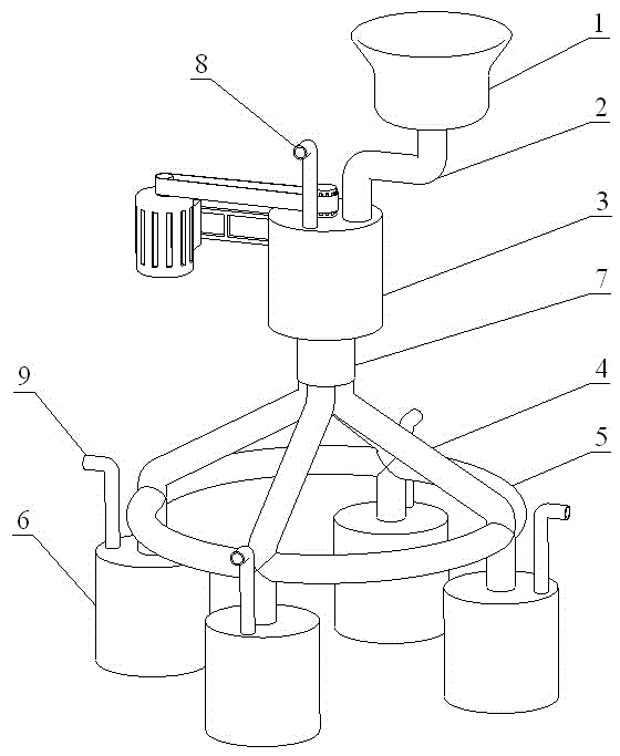
[0015] Embodiment 1 of the present invention: a casting pouring device, such as figure 1 As shown, it includes a gate 1, a first main flow channel 2, a stirring furnace 3, a runner 4, a uniform flow channel 5 and a mold 6, and the gate 1 is arranged above the stirring furnace 3, and the gate 1 and the stirring furnace 3 are formed by the first The main channel 2 is connected, the sub-runner 4 is arranged under the stirring furnace 3, the sub-runner 4 distributes the liquid metal to each mold 6, the uniform flow channel 5 is arranged at the lower part of the sub-runner 4, and the casting mold 6 is connected under the sub-runner 4.
[0016] In particular, the sub-runner 4 is connected to the stirred furnace 3 by a second main runner 7 .
[0017] Wherein, the number of runners 4 is four.
[0018] Moreover, the uniform flow channel 5 passes through all the flow distribution channels 4; the shape of the uniform flow channel 5 is circular.
[0019] In addition, the upper part of t...
Embodiment 2
[0020] Embodiment 2 of the present invention: a casting pouring device, comprising a gate 1, a first main flow channel 2, a stirring furnace 3, a runner 4, a uniform flow channel 5 and a casting mold 6, the gate 1 is arranged above the stirring furnace 3, The gate 1 and the stirring furnace 3 are connected by the first main flow channel 2, the runner 4 is arranged under the stirring furnace 3, the runner 4 distributes the liquid metal to each mold 6, and the uniform flow channel 5 is arranged at the lower part of the runner 4, The casting mold 6 is connected below the runner 4 .
[0021] Wherein, the number of runners 4 is three.
[0022] Moreover, the uniform flow channel 5 passes through all the flow distribution channels 4; the shape of the uniform flow channel 5 is triangular.
[0023] In addition, the upper part of the stirring furnace 3 is provided with a first exhaust hole 8; the upper part of the casting mold 6 is provided with a second exhaust hole 9.
Embodiment 3
[0024] Embodiment 3 of the present invention: a casting pouring device, comprising a gate 1, a first main flow channel 2, a stirring furnace 3, a runner 4, a uniform flow channel 5 and a casting mold 6, the gate 1 is arranged above the stirring furnace 3, The gate 1 and the stirring furnace 3 are connected by the first main flow channel 2, the runner 4 is arranged under the stirring furnace 3, the runner 4 distributes the liquid metal to each mold 6, and the uniform flow channel 5 is arranged at the lower part of the runner 4, The casting mold 6 is connected below the runner 4 .
[0025] Wherein, the number of runners 4 is two.
[0026] Moreover, the uniform flow channel 5 passes through all the branch flow channels 4; the uniform flow channel 5 is a straight pipe.
[0027] The use method of the present invention: pour the liquid metal into the gate 1, the liquid metal flows into the stirring furnace 3 through the first main channel 2, the evenly stirred liquid metal flows in...
PUM
 Abstract
Description
Claims
Application Information
 - Generate Ideas
- Intellectual Property
- Life Sciences
- Materials
- Tech Scout
- Unparalleled Data Quality
- Higher Quality Content
- 60% Fewer Hallucinations
Browse by: Latest US Patents, China's latest patents, Technical Efficacy Thesaurus, Application Domain, Technology Topic, Popular Technical Reports.
© 2025 PatSnap. All rights reserved.Legal|Privacy policy|Modern Slavery Act Transparency Statement|Sitemap|About US| Contact US: help@patsnap.com