Welding system for large thick-wall steel plate

A welding system and thick steel plate technology, applied in welding equipment, auxiliary welding equipment, welding/cutting auxiliary equipment, etc., can solve the problems of thick steel plate turning over, etc., to improve production efficiency, facilitate workers to operate, and the welding and turning process is stable and reliable Effect

Active Publication Date: 2015-04-01
GUIZHOU HUITONG SHENFA STEEL STRUCTURE
View PDF7 Cites 4 Cited by
  • Summary
  • Abstract
  • Description
  • Claims
  • Application Information

AI Technical Summary

Problems solved by technology

[0003] The technical problem to be solved by the present invention is to provide a welding device capable of turning over the steel plate during welding for the problem that the thick steel plate needs to be turned over during welding

Method used


Image

  • Welding system for large thick-wall steel plate
  • Welding system for large thick-wall steel plate
  • Welding system for large thick-wall steel plate

Examples


Embodiment 1

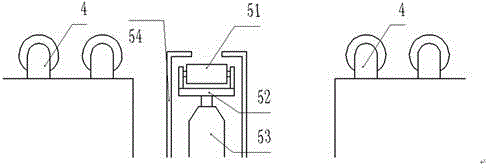
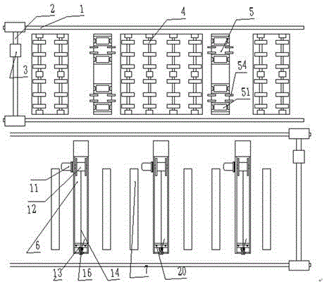
[0024] As shown in the figure, the gantry-type welding mechanism is composed of rail 1, row frame 2 and movable welding torch 3, and the welding torch can move up, down, left, and right in the plane. A steel plate support structure is arranged between the two rails 1, and the steel plate support structure is composed of three sets of idler rollers 4, each of which has two rows of idler rollers 4 in the left and right groups, and the central set has four rows of idler rollers 4. The steel plate support structure is used to place the steel plate to be welded, and the steel plate can be moved left and right by the supporting roller 4.

[0025] A lifting mechanism 5 is set between two adjacent groups of idlers 4, and the lifting mechanism 5 is composed of a roller 51 and a mounting frame 52, and the axis of the roller 51 is perpendicular to the axis of the idler 4. Four rollers 51 are installed on each mounting frame 52, and the mounting frame 52 is installed on the lifting hydrau...

Embodiment 2

[0029] The gantry-type welding mechanism is composed of a rail 1, a row frame 2 and a movable welding torch 3, and the welding torch can move up, down, left, and right in a plane. A steel plate support structure is arranged between the two rails 1, and the steel plate support structure is composed of four sets of rollers 4, the left and right groups each have two rows of rollers 4, and the central two groups have four rows of rollers 4. The steel plate support structure is used to place the steel plate to be welded, and the steel plate can be moved left and right by the supporting roller 4.

[0030] A lifting mechanism 5 is set between two adjacent groups of idlers 4, and the lifting mechanism 5 is composed of a roller 51 and a mounting frame 52, and the axis of the roller 51 is perpendicular to the axis of the idler 4. Four rollers 51 are installed on each mounting frame 52, and the mounting frame 52 is installed on the lifting hydraulic cylinder 53, and the limit frame 54 is...


PUM


Abstract

The invention discloses a welding system for a large thick-wall steel plate. The system comprises a portal type welding mechanism and a steel plate supporting structure. The system is characterized in that the steel plate supporting structure is arranged between two steel rails (1) of the portal type welding mechanism; the steel plate supporting structure is composed of a plurality of groups of carrier rollers (4) and is also equipped with a holding mechanism (5) which is mounted on a lifting hydraulic cylinder (53); an overturning bracket (6) which is hinged to a supporting seat (16) is arranged at one side of the portal type welding mechanism, and the overturning bracket (6) is that the rear surface is connected with a rotating hydraulic cylinder (18), the bottom part is equipped with a steel wire coil (12), and the top part is equipped with a fixed pulley (16); the steel wire coil (12) is connected with a motor (11). With the adoption of the welding system, the abutting, welding, side overturning and other processes in the welding process of a thick steel plate can be done; the stability and reliability in welding and overturning are ensured; workers can operate conveniently; the production efficiency is raised.

Description

technical field [0001] The invention relates to a device for welding large steel plates. Background technique [0002] When welding thick steel plates, the front and back sides need to be welded alternately, and it is very difficult to turn over large thick-walled steel plates. Usually, the steel plates are hoisted and turned over by using a crane. This method has serious safety hazards, and the steel plates are easy to fall off and damage the operation. personnel. Contents of the invention [0003] The technical problem to be solved by the present invention is to provide a welding device capable of turning over the steel plate during welding for the problem that the thick steel plate needs to be turned over during welding. [0004] Technical scheme of the present invention is: [0005] A welding system for large-scale steel plates, including a gantry-type welding mechanism and a steel plate support structure, the steel plate support structure is arranged between two rai...

Claims


Application Information

Patent Timeline
Patent Type & Authority Applications(China)
IPC IPC(8): B23K37/047
CPCB23K37/047B23K2101/185B23K2103/04
Inventor 朱方正罗俊武瑞胡志鹏胡仕坤
Owner GUIZHOU HUITONG SHENFA STEEL STRUCTURE
Why Eureka
Try Eureka