Speed boat

A technology for speedboats and hulls, which is applied to ships, ship parts, auxiliary equipment, etc., can solve the problems of normal operation, reduce the effective area of ​​the fluid channel of the water-air separation device 12, and reduce the speed of the speedboat.

Active Publication Date: 2015-04-01
珠海横琴琛龙恒远船舶科技有限公司
View PDF6 Cites 0 Cited by
  • Summary
  • Abstract
  • Description
  • Claims
  • Application Information

AI Technical Summary

Problems solved by technology

But the vane 121 on the louver reduces the effective area of ​​the fluid channel of the water-air separation device 12. In order to meet the demand of the equipment for the air supply, it is necessary to increase the windward area of ​​the inlet, and the louver with a large area will

Method used


Image

  • Speed boat
  • Speed boat
  • Speed boat

Examples


no. 1 example

[0028] The speedboat in this example has a hull and engine room ventilation system, and the engine room ventilation system is used to supply air to the engine room to meet the oxygen consumption demand of the internal combustion engine and the cooling demand of the equipment in the engine room.

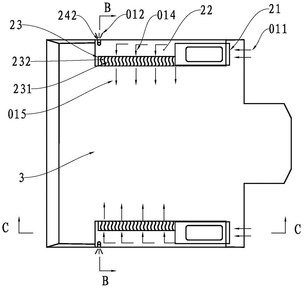
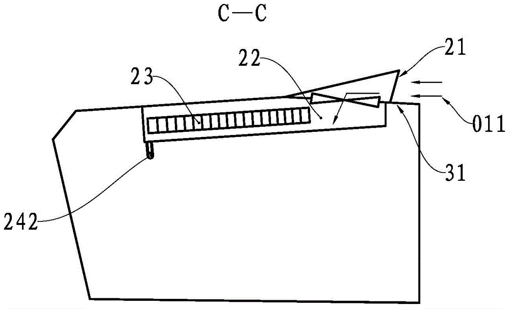
[0029] see Figure 2 to Figure 4 , The engine room ventilation system is composed of two ventilation units located symmetrically on both sides of the hull. The ventilation unit is composed of an inlet 21, a settling device 22, a water-air separation device 23, a drainage device and an outlet. The inlet 21 is located on the engine room deck 31 and the opening faces the bow of the boat. The settling device 22 is a chamber attached to the narrow and long structure on the inside of the side of the engine room. The water and air separation device 23 is located on the side of the settling device 22 away from the side, and it is composed of a plurality of S-shaped water baffles 231 arranged...

no. 2 example

[0037] As an explanation of the second embodiment of the present invention, only the differences from the above-mentioned first embodiment will be described below.

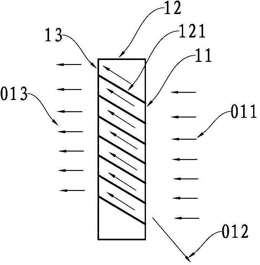
[0038] see Figure 6 , the fluid channel formed between two adjacent water barriers 431 of the water-gas separation device has a C-shaped bend 4321, and the fluid 014 will change its traveling direction at the bend 4321, and the water in it will collide with the water barrier under the action of centrifugal force. Gathered on the side wall of the plate 431.

[0039] In this example, the area of ​​the inlet of the fluid channel is the sum of the effective cross-sectional areas 032 of all individual fluid channels.

no. 3 example

[0041] As a description of the third embodiment of the present invention, only the differences from the above-mentioned first embodiment will be described below.

[0042] see Figure 7 The fluid channel formed between two adjacent water baffles 531 of the water-air separation device has three bends, so that the moisture in the fluid 014 is subjected to centrifugal force three times, thereby reducing the moisture content of the air 015 entering the cabin.

[0043] In this example, the area of ​​the inlet of the fluid channel is the sum of the effective cross-sectional areas 033 of all individual fluid channels.


PUM


Abstract

The invention relates to a speed boat. The speed boat comprises a boat body and an engine room ventilation system; the engine room ventilation system comprises two ventilation units which are symmetrically arranged on two sides of the boat body; each ventilation unit sequentially comprises an inlet, a moisture separating device and an outlet along a fluid advancing direction; the inlets are formed in an engine room deck; openings of the inlets are towards a boat bow; the length direction of the moisture separating device is arranged along the length direction of the boat body; each ventilation unit also comprises a drainage device and a settling device which is arranged at the upstream of the corresponding moisture separating device; each drainage device comprises a collector and a drainage opening which is communicated with the collector; each collector comprises a bottom surface of a fluid channel of the moisture separating device and a bottom surface of a chamber; each drainage opening is formed in the external lateral side of a board side; the outlets comprise air outlets of the fluid channels and the drainage openings of the drainage devices. Compared with the existing speed boat, air resistance generated by the engine room ventilation system of the speed boat to the boat body is relative small and improvement of the navigational speed of the speed boar is facilitated.

Description

technical field [0001] The invention relates to a ship equipped with ventilation auxiliary equipment in the engine room, in particular to a speedboat with an improved engine room ventilation system. Background technique [0002] In order to increase the speed of the speedboat, it is necessary to control its weight and meet the corresponding layout requirements. The cabin space is usually small, and the power and volume of the equipment in the cabin are relatively large. During high-speed navigation, a large amount of air needs to be added to the cabin to meet Oxygen consumption of the internal combustion engine and equipment cooling requirements; Due to the limitation of space and equipment, natural ventilation is usually used, so it is necessary to design an air inlet facing the wind in the forward direction, but the hull of a speedboat is generally low, and seawater is easy to flow from the air during high-speed navigation. The air intake pours into the cabin. [0003] In...

Claims


Application Information

Patent Timeline
IPC IPC(8): B63J2/02
Inventor 梁荣宇梁明森
Owner 珠海横琴琛龙恒远船舶科技有限公司
Why Eureka
Try Eureka