Clock circuit for frequency division by adopting trigger

A technology of clock circuit and frequency division circuit, which is applied in the direction of TV, electrical components, color TV, etc., can solve the problems of occupying image acquisition board and unfavorable miniaturization design, and achieve the effect of reducing area and facilitating miniaturization design

Inactive Publication Date: 2015-04-01
CHENGDU SHENGJUN ELECTRONICS EQUIP
View PDF2 Cites 2 Cited by
  • Summary
  • Abstract
  • Description
  • Claims
  • Application Information

AI Technical Summary

Problems solved by technology

At present, multiple crystal oscillator circuits in this structure need to occupy a certain area of ​​the image acquisition board, which is not conducive to miniaturization design

Method used


Image

  • Clock circuit for frequency division by adopting trigger
  • Clock circuit for frequency division by adopting trigger
  • Clock circuit for frequency division by adopting trigger

Examples


Embodiment 1

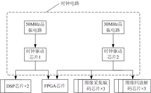
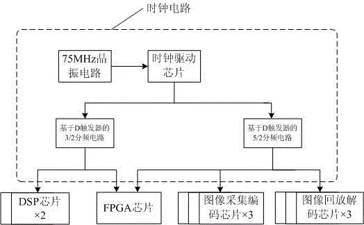
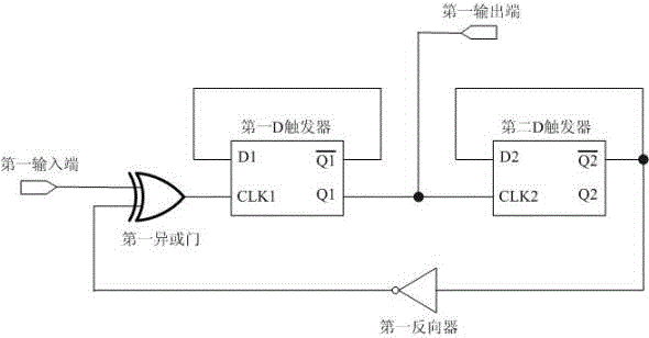
[0020] Embodiment one, figure 2 It shows the structure diagram of the clock circuit based on the flip-flop frequency division provided by this embodiment, image 3 A 3 / 2 frequency division circuit diagram based on a D flip-flop in the clock circuit provided by this embodiment is shown, Figure 4 A 5 / 2 frequency division circuit diagram based on a D flip-flop in the clock circuit provided by this embodiment is shown, Figure 5 The working waveform diagram of the 3 / 2 frequency division circuit based on the D flip-flop provided in this embodiment is shown, Figure 6 The working waveform diagram of the 5 / 2 frequency division circuit based on the D flip-flop provided by this embodiment is shown. The described clock circuit using flip-flop frequency division is characterized in that it comprises: a crystal oscillator circuit, a clock driver chip, and two frequency division circuits based on flip-flops; the crystal oscillator circuit is connected to the clock driver chip, and the ...


PUM


Abstract

The invention relates to the field of an image acquisition plate, and discloses a clock circuit for frequency division by adopting a trigger. The clock circuit for frequency division by adopting the trigger is only equipped with a crystal oscillation circuit and a plurality of frequency dividing circuits based on the trigger; the frequency division is carried out on a clock signal produced by the crystal oscillation circuit with the frequency dividing circuits based on the trigger, thus, the aim of providing the clock signal with different frequencies for a plurality of modules on the image acquisition plate is realized. Since the frequency dividing circuits based on the trigger are digital circuits and a few area of a circuit board is only occupied by adopting an integrated circuit, the clock circuit provided by the invention can reduce the occupation area of the image acquisition plate, so the miniaturization design is facilitated.

Description

technical field [0001] The invention relates to the field of image acquisition boards, in particular to a clock circuit using flip-flops for frequency division. Background technique [0002] Frame acquisition card, also known as image capture card, is a hardware device that can acquire digital video image information, store and play it out. The structure of the image acquisition card mainly includes an acquisition input module, an analog-to-digital conversion (A / D) module, an image processing module, a digital-to-analog conversion (D / A) module, a playback output module and a bus interface module. The conversion (A / D) module and the image processing module complete the process of sampling, quantizing and converting the image / video into digital video image information, the image processing module, and the digital-to-analog conversion (D / A) module complete the digital video image information The process of decoding and outputting the playback image or video, the image processi...

Claims


Application Information

Patent Timeline
Patent Type & Authority Applications(China)
IPC IPC(8): H04N5/232H03K23/00
Inventor 肖燕吴东
Owner CHENGDU SHENGJUN ELECTRONICS EQUIP
Why Eureka
Try Eureka