Pull rod machining technology

A processing technology and tie rod technology, applied in the field of tie rod processing technology, can solve the problems of insufficient tie rod strength, unfavorable production, insufficient tie rod hole accuracy, etc., and achieve the effects of reducing production cost, reducing defective rate and improving accuracy.

Inactive Publication Date: 2015-04-08
SUZHOU FUMAI PRECISION MACHINERY
View PDF5 Cites 2 Cited by
  • Summary
  • Abstract
  • Description
  • Claims
  • Application Information

AI Technical Summary

Problems solved by technology

[0002] There are many methods for making tie rods, but there are some problems, such as insufficient strength of the tie rods, insufficient hole precision of the tie rods, and the overall shape of the tie rods does not mee

Method used


Image

  • Pull rod machining technology

Examples


Embodiment 2

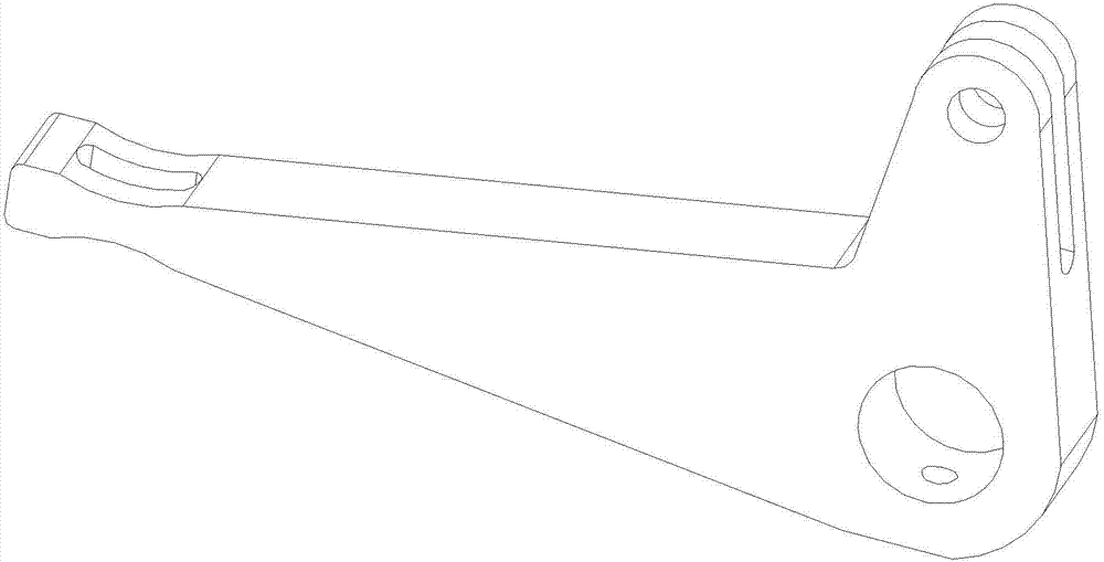
[0012] Embodiment 2: the first step: cut the material with a laser cutting machine, and initially cut out the shape of the product according to the size of the drawing, which is L-shaped, 185mm long, 95mm wide, and 23mm thick, and the shape of the product is initially determined; Step 2: Use a milling machine to perform positioning processing on the cut product, and drill a round hole at a distance of 21.5mm from the bottom of the product and 22.5mm on the side, with a diameter of φ25mm, and perform positioning processing according to the requirements of the drawing; Step 3: Mill the hole with a milling machine , and the upper end of the φ25mm round hole, drill a φ10mm round hole at a distance of 60mm, and process according to the drawing; the fourth step: use a milling machine to further process the material, and on the material at a center distance of 143.5mm from the φ25mm round hole For processing, mill R20 arcs on the upper and lower ends of the surface, the length is 20mm...

Embodiment 3

[0013] Embodiment three: the first step: cut the material with a laser cutting machine, and initially cut out the shape of the product according to the size of the drawing, which is L-shaped, 185mm long, 95mm wide, and 23mm thick, and the shape of the product is initially determined; Step 2: Use a milling machine to perform positioning processing on the cut product, and drill a round hole at a distance of 21.5mm from the bottom of the product and 22.5mm on the side, with a diameter of φ25.2mm, and perform positioning processing according to the drawing requirements; Step 3: Use a milling machine Mill the hole, drill the upper end of the φ25.2mm round hole, drill the φ10.18mm round hole at the middle distance of 60.2mm, and process it according to the drawing; the fourth step: use a milling machine to further process the material, and drill the φ25.2mm round hole The material at the center distance of 143.5mm is processed, and the surface of the upper and lower ends is milled wi...


PUM


Abstract

The invention discloses a pull rod machining technology. The pull rod machining technology includes the steps of 1, cutting materials by a laser cutting machine to form an L-shaped product outline preliminarily according to the drawing size; 2, subjecting the cut product to positioning and machining by a milling machine; 3, using the milling machine for hole milling; 4, further machining the materials by the milling machine; 5, using the milling machine for milling an elongated slot in the surface in which an R20 circular arc is positioned; 6, using the milling machine for side face hole milling; 7, subjecting the materials to linear cutting; 8, subjecting the materials to finish milling, namely, finish machining according to drawing requirements on the size and shape; 9, rounding off the materials according to drawing requirements; 10, subjecting a machined product to surface polishing; 11, product inspection and warehousing. The pull rod machining technology has the advantages that production requirements are met, precision and strength of the produced pull rod are improved to meet the requirements, defective percentage is decreased and production cost is lowered.

Description

technical field [0001] The invention relates to a processing technology of a tie rod, which belongs to the technical field of mechanical processing. Background technique [0002] There are many methods for making tie rods, but there are some problems, such as insufficient strength of the tie rods, insufficient hole precision of the tie rods, and the overall shape of the tie rods does not meet the requirements, etc. Such tie rods cannot meet market demand and are not conducive to production Therefore, in order to better meet the requirements of the tie rod, a processing method is proposed to solve this problem. Contents of the invention [0003] In view of the above-mentioned technical problems, the object of the present invention is to propose a processing technology for a tie rod with precise processing accuracy and satisfactory size. [0004] The technical solution of the present invention is realized in the following way: a processing technology of a pull rod, the firs...

Claims


Application Information

Patent Timeline
IPC IPC(8): B23P15/00
CPCB23P15/00
Inventor 顾卫建
Owner SUZHOU FUMAI PRECISION MACHINERY
Why Eureka
Try Eureka