
Paper-cutting crankshaft unit

A technology of paper cutting device and crankshaft, which is applied in metal processing and other directions, can solve the problems of paper cutting failure and achieve the effect of convenient cutting

Inactive Publication Date: 2015-04-08
NANTONG SITONG FORESTRY MACHINE MFG INSTALLATION
View PDF7 Cites 1 Cited by
  • Summary
  • Abstract
  • Description
  • Claims
  • Application Information

AI Technical Summary

Problems solved by technology

[0011] However, when cutting paper, the cutting knife and the lower knife need to be fully matched together to complete the function of paper cutting. There are slight deviations, such as: the cutting knife is not rotated in place, the lower knife is not adjusted in place, and the edge of the cutting knife and the lower knife are not meshed. And so on will lead to paper cutting failure

Method used


Image

  • Paper-cutting crankshaft unit

Examples


Embodiment Construction

[0029] The present invention is described in further detail now in conjunction with accompanying drawing. These drawings are all simplified schematic diagrams, which only illustrate the basic structure of the present invention in a schematic manner, so they only show the configurations related to the present invention.

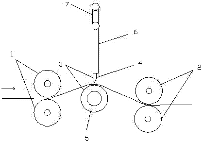
[0030] Such as figure 1 As shown, a crankshaft paper cutting device includes two mutually matched paper feed rollers 1 and two mutually matched paper output rollers 2, and a paper cutting mechanism 3 is arranged between the paper feed roller 1 and the paper output roller 2, The paper cutting mechanism 3 includes a cutter 4 and a rubber roller 5 arranged directly below the cutter 4. The cutter 4 is arranged at the lower end of the connecting rod 6, and the connecting rod 6 is sleeved on the crankshaft through a bearing sleeve. 7, the crankshaft 7 is driven by a motor, and the cutter 4 moves up and down driven by the crankshaft 7 and the connecting rod 6.

[0...


PUM


Abstract

The invention discloses a paper-cutting crankshaft unit comprises two feed rollers and two discharge rollers. The feed rollers fit each other; the discharge rollers fit each other. A cutting mechanism is disposed between the feed rollers and the discharge rollers and comprises a cutting blade and a rubber roller disposed right under the cutting blade. The cutting blade is disposed at the lower end of a connecting bar; the connecting bar is in sleeving connection with a crankshaft through a bearing; the crankshaft is driven by a motor; the cutting blade is driven by the crankshaft and the connecting bar to move up and down. Compared with the prior art, the paper-cutting crankshaft unit has the advantages that cutting position of paper is accurate, noise is low, and work efficiency is high.

Description

technical field [0001] The invention relates to a crankshaft paper cutting device. Background technique [0002] Paper cutters are used to cut paper rolls into pieces. There are many kinds of paper cutters, such as the gate knife for cutting up and down, the swing knife for intermittent cutting, etc. Although the cutting quality of the paper edge is relatively poor Good, but the paper must be stopped, and the paper can continue to be fed after cutting. The paper feeding speed cannot be fast, and the production efficiency is very low; although the swinging knife can feed the paper continuously, the mechanical impact at the moment of cutting is relatively large, which may easily cause damage to the mechanical equipment. Damage and noise pollution, at the same time, the speed of paper feeding should not be too fast, and the length of paper sheets should not be too short, otherwise there is no time to stop the knife in the middle, resulting in inaccurate length of paper cutting....

Claims


Application Information

Patent Timeline
Patent Type & Authority Applications(China)
IPC IPC(8): B26D1/06B26D7/28B26D7/14B26D5/00
Inventor 陆新明王建清李金炎朱玲
Owner NANTONG SITONG FORESTRY MACHINE MFG INSTALLATION
Learn More