Hydraulic floatingsnap ring lock
A clasp lock and hydraulic lock technology, which is applied in the direction of fluid pressure actuating devices, can solve the problems of accelerating the wear of the sealing device, the wear of the steel ball hole and the lock groove, and affecting the accuracy of the measurement, so as to increase the force-bearing contact surface Effect
- Summary
- Abstract
- Description
- Claims
- Application Information
AI Technical Summary
Problems solved by technology
Method used
Image
Examples
Embodiment Construction
[0018] The present invention will be further described below in conjunction with the accompanying drawings and embodiments, but the present invention is not limited to the scope of the described embodiments. All these concepts should be regarded as the contents disclosed in this technology and the protection scope of the present invention.
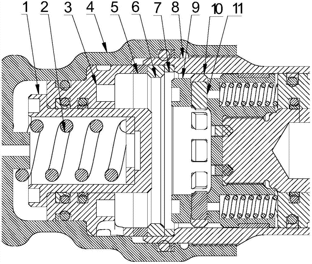
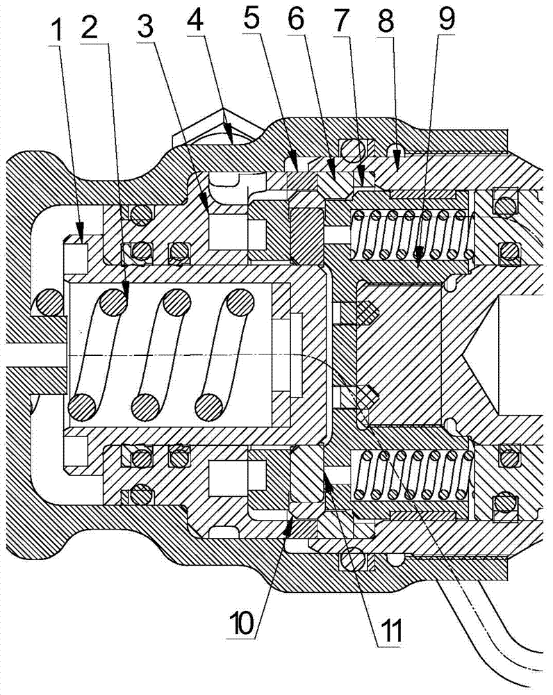
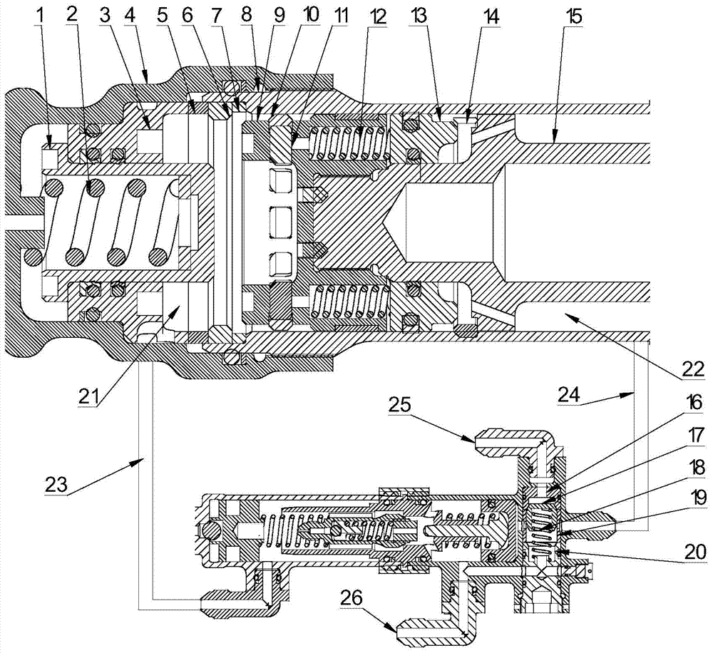
[0019] refer to Figure 1 ~ Figure 3 . In the embodiment described below, the hydraulic hydraulic floating snap ring lock is mainly composed of a spring seat 1, a first spring 2, a support seat 3, an actuator end cover 4, a first gasket 5, a snap ring seat 6, a second gasket Sheet 7, outer cylinder 8, retainer 9, first spring coil 10, floating slider group 11. The shuttle valve integrated on the hydraulic lock is mainly composed of a first shuttle valve seat 16, a shuttle valve core 17, a second spring 18, a shuttle valve sleeve 19, and a second shuttle valve seat 20. Specifically, the hydraulic floating snap ring lock includes a suppor...
PUM
 Abstract
Description
Claims
Application Information
 - R&D
- Intellectual Property
- Life Sciences
- Materials
- Tech Scout
- Unparalleled Data Quality
- Higher Quality Content
- 60% Fewer Hallucinations
Browse by: Latest US Patents, China's latest patents, Technical Efficacy Thesaurus, Application Domain, Technology Topic, Popular Technical Reports.
© 2025 PatSnap. All rights reserved.Legal|Privacy policy|Modern Slavery Act Transparency Statement|Sitemap|About US| Contact US: help@patsnap.com


