
Deceleration and speed change integrated face gear pair and processing method thereof

A face gear, deceleration and speed change technology, which is applied in the field of non-circular gear transmission pairs and processing, can solve the problems of inability to realize deceleration and speed reduction integrated transmission, and can not realize deceleration and speed change transmission, so as to improve transmission efficiency and precision, shorten transmission chain, Reduce the effect of transmission parts

Inactive Publication Date: 2015-04-08
YANSHAN UNIV
View PDF9 Cites 12 Cited by
  • Summary
  • Abstract
  • Description
  • Claims
  • Application Information

AI Technical Summary

Problems solved by technology

The period of the pitch curve of the elliptical gear is 1. When the period of the pitch curve of the special face gear is an integer greater than 1, deceleration and variable speed transmission can be realized, but like other types of non-circular gear pairs, the deceleration of the non-circular gear pair The ratio is limited by the number of output angular velocity cycles, so it is impossible to achieve any deceleration and variable transmission effect
[0006] To sum up, at present, all types of non-circular gears cannot realize the integrated transmission of arbitrary reduction and transmission. The fundamental reason is that the shapes of the two gears in the non-circular gear pair are non-circular, which determines the size of the reduction ratio. The number of cycles of the transmission ratio and the transmission ratio are mutually limited, so that the integrated transmission of deceleration and transmission cannot be realized

Method used


Image

  • Deceleration and speed change integrated face gear pair and processing method thereof
  • Deceleration and speed change integrated face gear pair and processing method thereof
  • Deceleration and speed change integrated face gear pair and processing method thereof

Examples


Embodiment Construction

[0045] The present invention will be further described below in conjunction with accompanying drawing:

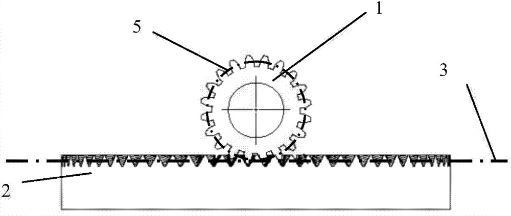
[0046] figure 1 It is the front view of the small cylindrical gear 1 and the face gear 2 after assembly, the small cylindrical gear and the face gear rotate around a fixed axis, and the rotation axes of the two are orthogonal. The cylindrical surface where the index circle of the small cylindrical gear is located is the pitch cylindrical surface 5 of the small cylindrical gear, the pitch surface 3 of the face gear is a plane, and the pitch cylindrical surface is tangent to the pitch surface.

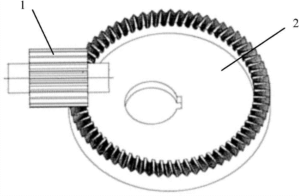
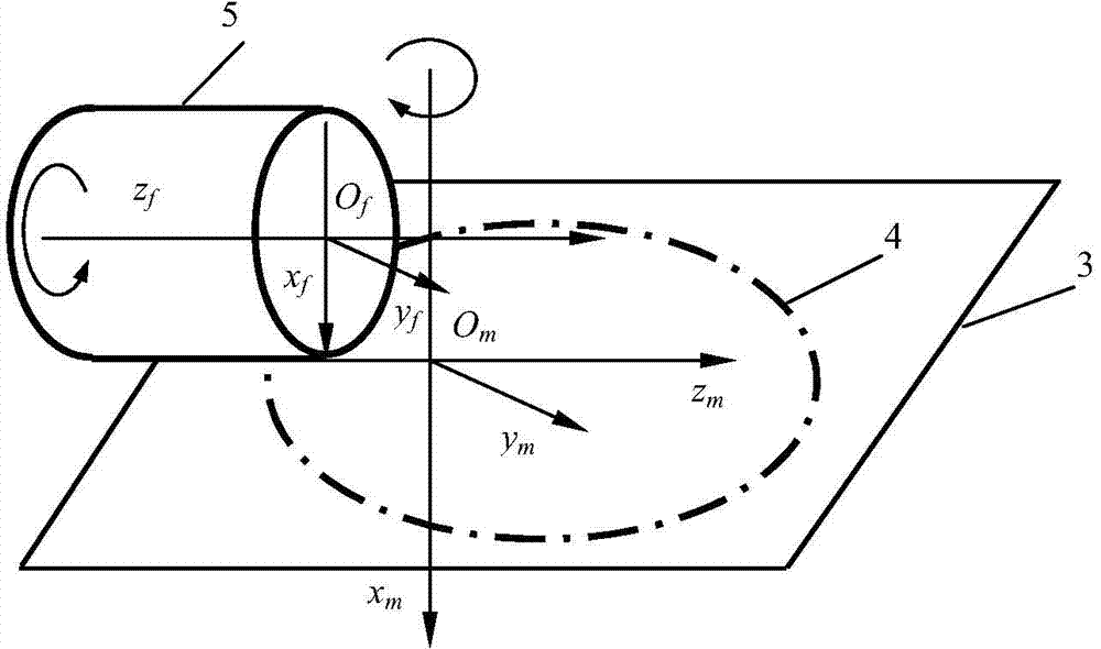
[0047] figure 2 is the assembly diagram of the small cylindrical gear and the face gear, and the pitch curve 4 of the face gear is a plane curve on the pitch surface, such as image 3 shown. When the small cylindrical gear and the face gear rotate relatively, the pitch cylindrical surface and the pitch curve keep pure rolling, then the transmission ratio i realized by the small cy...


PUM


Abstract

The invention relates to a deceleration and speed change integrated face gear pair and a processing method thereof. The deceleration and speed change integrated face gear pair comprises a drive gear and a driven gear, wherein the drive gear is a small cylindrical gear; the driven gear is a non-cylindrical face gear; gear teeth of the face gear are uniformly distributed on the edge of the end surface of the face gear; the pitch surface of the face gear is a plane and is perpendicular to a rotation axis of the face gear, and a pitch curve of the face gear is a non-circular curve on the pitch surface of the face gear; a cylindrical surface on which a divided circle on the small cylindrical gear is positioned is a pitch cylindrical surface, the rotation axis of the small cylindrical gear with straight teeth is orthogonal to that of the face gear and the small cylindrical gear is meshed with the face gear; the pitch cylindrical surface of the small cylindrical gear is tangential to the pitch surface of the face gear, and the pitch cylindrical surface of the small cylindrical gear is in contact with a pitch curve point of the face gear and keeps pure rolling. The face gear can be processed by a gear slotting tool through gear shaping, and the process of enveloping the gear teeth of the face gear through the gear slotting tool is similar to the transmission process of the face gear pair. The deceleration and speed change integrated face gear pair has the advantages that the transmission mechanism is simplified, the transmission efficiency is improved, and the transmission space is saved.

Description

technical field [0001] The invention relates to the field of transmission machinery, in particular to a non-circular gear transmission pair and a processing method. Background technique [0002] In the field of mechanical transmission, transmission with variable speed ratio occupies a very large proportion. Many applications require equipment with variable speed ratio transmission function to achieve specific process requirements. Among many variable speed ratio transmission mechanisms, non-circular gear pairs have the transmission characteristics of cams and gears, which can achieve high efficiency and high-power precise transmission ratios, so they have been widely used in agricultural machinery, metallurgical machinery, printing machinery and textile machinery. Wide range of applications. Since the prime mover of the equipment is generally an electric motor, the speed is too high to be directly connected with the variable speed transmission mechanism to output variable ...

Claims


Application Information

Patent Timeline
IPC IPC(8): F16H1/12
CPCB23F5/12F16H1/12F16H55/08F16H55/088F16H55/17
Inventor 刘大伟任廷志
Owner YANSHAN UNIV
Learn More